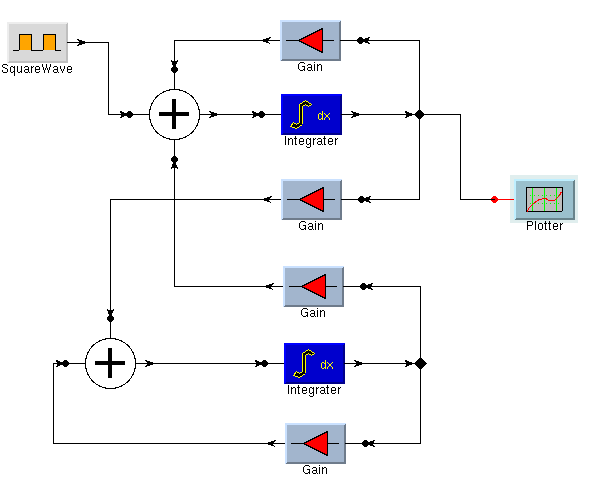

Figure 10 shows a snapshot of one of the graphical editors constructed using the Slate. This editor is the front-end for Ptolemy II, a new version of Ptolemy [6] being written in Java. The particular system shown is a second-order continuous-time simulation, written by Jie Liu of UC Berkeley. In this editor, icons can be selected from a library stored as ASCII text, which describes each icon in terms of the ComplexItem type used to draw it, the number and location of terminals, the label, and the graphics to draw upon the surface of the icon.
Once placed, icons can be selected and moved around. (This is done using the Selector and Follower interactors.) When the mouse moves over an unconnected terminal of an icon, a DragDropper interactor is activated, which highlights the terminal to indicate that it is ``ready.'' If the mouse is clicked on the terminal, the DragDropper creates a new SmartLine item, and reshapes the line so that the end follows the cursor. When the end of the line moves over a terminal, the DragDropper activates a call-back to test if the terminal is a suitable ``drop target.'' If it is, it snaps [4] the end of the line to the connection point of the terminal, altering the shape of the line to make it join at the expected angle.
Figure 10: A snapshot of a graphical editor
Internally, this graphical editor uses a variant of the model-view-controller architecture (see, for example, [1]). As the user places icons and connects terminals, the interactors forward events to either an edge controller or a vertex controller. The architecture is shown in figure 11. The controller first decides what the user interaction means in terms of the underlying semantics of the visual program, and modifies the semantic model accordingly (in this example, the semantic model is a directed graph). The controller also decides what visual aspects of the program have changed, such as moving the end of a line, or adding a new icon. It modifies the layout model accordingly, which in turn notifies the view containing the slate, which in turn updates to reflect the new appearance.
This seems, at first, somewhat complicated, but our experience indicates that it does leads to highly modular and customizable editors. We are, however, still gaining experience with this architecture. Interactive response is very good, partly because the interactor model is able to optimize incremental mouse movements while items are being dragged about on the screen.
Figure 11: The architecture of a graphical editor
Finally, we note here our observations on the use of constraints, as included in many experimental toolkits ([8, 9], for example). In constraint systems, the programmer sets up constraints between graphical items, which the constraint system attempts to maintain as conditions change. For example, our editor could have constraints set up such that the ends of attached lines move when an icon is moved.
We wrote a simple constraint system early on, and found that writing constraints to catch the right conditions and to avoid cycles was tricky. We ended up trashing the constraint system - simple though it was - when we realized that the model-view-controller architecture offers a better and simpler alternative. If you look at figure 11, you can see that, as an icon is moved, the layout model must be modified for attached edges as well as the icon. How do we know what edges to move? Why, by looking at the semantic model!
Thus, we concluded that, in interfaces that have an underlying semantic model, using that model with an appropriate controller object is a more straight-forward solution than general-purpose constraint solvers. In addition, since we have a comprehensive set of interactors, it is also straight-forward to implement purely-syntactic constraints by appropriately configuring interactors. For example, keeping the slider in figure 8 on the right track does not require constraints, just the right interactor.