


Next: Planning and Global Reconfiguration
Up: Distributed Adaptation in CANS
Previous: Intra-Component Adaptation using Distributed
Data Path Reconfiguration and
Error Recovery using Semantic Segments
Insertion, deletion, or reordering of drivers along an active data
path provides great flexibility in responding to a range of resource
variations and link/node failure. However, a fundamental problem is
that any such reconfiguration must preserve application semantics. In
this paper, we focus on maintaining semantic continuity and
exactly-once semantics. Specifically, any scheme must take into
account the fact that the portion of the data path affected by the
reconfiguration can have stream data that has been partially
processed: in the internal state of drivers, in transit between
execution environments, or data that has been lost due to failures.
Note that although the soft-state requirement discussed in
Section 3.1 permits us to restart a driver, it
does not provide any guarantees on semantic loss or in-order
reception.
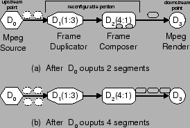
Figure 5 shows an example highlighting this problem.
To introduce some terminology, we refer to the portion of the data
path that needs to be reconfigured because of a change in system
conditions on the physical nodes or links (failures are an extreme
example) as the reconfigurable portion, and the components
immediately upstream and downstream of this portion with respect to
the data path as the upstream point and downstream point
respectively.1
In the example, driver  is a source of MPEG data, driver
 is an MPEG frame duplicator which produces 3 frames for each
incoming frame, driver
is an MPEG frame duplicator which produces 3 frames for each
incoming frame, driver  is an MPEG frame composer which
generates one MPEG frame upon receiving four incoming frames from
, and
is an MPEG frame composer which
generates one MPEG frame upon receiving four incoming frames from
, and  is a renderer of MPEG data. The reconfigurable
portion consists of drivers and . Consider a situation
where system conditions change after the upstream point has
output two frames, and the downstream point has received one
frame. At this point, the data path portion containing and
cannot be reconfigured because doing so affects semantic
continuity. The reason is that because of partially processed data in
that portion, it is incorrect to retransmit either the second segment
from whose effects have been partially observed at , or
the third segment, which would result in a loss of continuity at
.
is a renderer of MPEG data. The reconfigurable
portion consists of drivers and . Consider a situation
where system conditions change after the upstream point has
output two frames, and the downstream point has received one
frame. At this point, the data path portion containing and
cannot be reconfigured because doing so affects semantic
continuity. The reason is that because of partially processed data in
that portion, it is incorrect to retransmit either the second segment
from whose effects have been partially observed at , or
the third segment, which would result in a loss of continuity at
.
Figure 5:
An example of data path
reconfiguration using semantics segments.
 |
The CANS infrastructure supports semantics preserving data path
reconfiguration and error recovery by leveraging two restrictions
placed on driver functionality, specifically semantic segments and
soft state (see Section 3.1).
Informally, the first restriction permits the infrastructure to infer
which segments arriving at the downstream point of the reconfigurable
portion depend on a specific segment injected at the upstream point
and vice-versa, while the second makes it always possible, even if any
internal driver state is reset, to recreate the same output segment
sequence at the downstream point by just retransmitting selected input
segments at the upstream.
Our solution exploits these characteristics to provide the required
guarantees by just combining buffering and delayed forwarding of
semantic segments at the upstream and downstream points respectively
with selective retransmission of segments that are incompletely
delivered. The correspondence between upstream and downstream segments
is completely determined by driver characteristics in the
reconfigurable portion; the implementation just needs to track marker
messages that demarcate segment boundaries.
This scheme uniformly handles both the situation where drivers
continue error-free operation but the data path needs to be
reconfigured in response to system conditions, as well as the
situation where link or node errors cause partial driver state to
be lost. For the first situation, we defer reconfiguration to the
time when the system can guarantee continuity and exactly once
semantics. When some CANS events trigger reconfiguration, the
upstream point starts buffering segments while continuing to
transmit them, in effect flushing out the contents of
intermediate drivers. The downstream point monitors the output
segments arriving there, waiting until it completely
receives an output segment satisfying the property
that all subsequent segments correspond only to input segments
either buffered at the upstream point or not yet transmitted. At
this time, the system can be stopped and the reconfigurable portion
replaced by a semantically equivalent set of drivers. To restart, the
upstream point retransmits starting from the first segment whose
corresponding output segment was not delivered.
The same basic scheme also permits error recovery on portions of
the data path that can be tagged a priori as possible sources of
failure. The upstream point by default buffers all input segments
before passing them on. The downstream point delays passing to the
downstream driver any output segments that cannot be
reconstructed in their entirity from input segments that are
buffered at the upstream point, effectively isolating the
downstream drivers from any duplicates that might get produced
due to retransmission. When it is safe to pass on an output
segment, the corresponding buffered input segments can be
discarded. Upon an error, the affected components are
re-instantiated, any buffered output segments at the downstream
points discarded, and retransmission resumed from the first input
segment whose corresponding output segment was never observed by
the downstream driver. This scheme can be trivially extended to
permit error recovery on portions that include services with
checkpoint/restart facilities: the service needs to checkpoint
whenever it produces a segment that corresponds to an input
segment boundary.
In our example, reconfiguration works as follows:
- The upstream point () starts buffering every segment it
sends out after this time.
- When downstream point () receives a complete segment from
the upstream point (in this case this happens the third segment
output by is received), it raises an event to the plan
manager.
- The plan manager can now freeze , and replace and
with a compatible driver graph.
- To restart, retransmits starting from segment 5. In this
case does not need to discard anything.
Error recovery on this portion requires to buffer its
output segments and have the downstream point pass on segments to
only in units of 3 segments at a time.
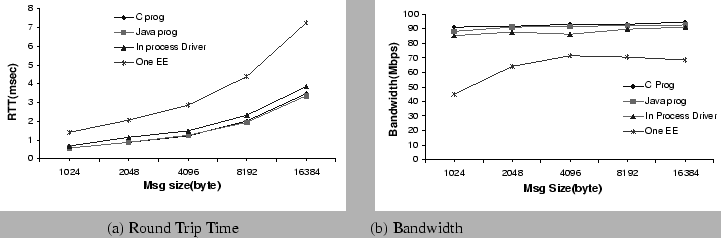
Figure 6:
Latency and bandwidth impact of the
CANS infrastructure.
 |
Next: Planning and Global Reconfiguration
Up: Distributed Adaptation in CANS
Previous: Intra-Component Adaptation using Distributed
Weisong Shi
2001-01-08