 |
Before and after the installation of the node hardware a number of basic alignment, throughput, and reliability tests have to be run. These tests are used to be sure that the links in the set-up will operate as expected. The expectation values for these tests are derived from the site survey and simulation results as described in section 2.4. The alignment test comprises of monitoring the signal strength and noise figure when a backbone link is established. By physically varying the antenna direction the signal as seen by the driver software on the wireless interface should be maximized, while the reported noise is minimized. Throughput and reliability is tested by transferring large chunks of data from one node to its neighbor and observing the packet loss and transfer rate.
Often, once the node is set up it is quite difficult to physically access the machine and the antennas because they mostly are located at remote locations and in buildings with complex access procedures. A typical test for the reliability is to copy some video data (often comprised of large files) through the node. This test differs from the test mentioned above where a single wireless link is tested, here the complete (routing) functionality of a node is tested. A test protocol is used to assure the repeatability of the test procedures.
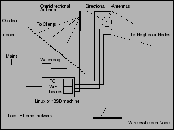
An external hardware watchdog device is used to ensure a reboot of the system when some part of the software crashes. These watchdog devices are home built and very simple. The watchdog watches the serial port of the node computer for a ``hello'' string. This string has to be sent every minute (using a small program or even a script). If this string is not received within 90 seconds of the previous string, the watchdog circuit will cut the power to the setup and will turn it on after a minute. Using either journaling file systems or RAM based file systems minimizes problems caused by a fsck operation after the setup has been powercycled.
The software environment on the machines is a standard Open Source free UNIX (currently FreeBSD) distribution stripped down to fit in a minimal hardware configuration. The (kernel) device drivers that are used to control the wireless network cards and some network operations and management utilities are added (ref. section 2.10).
Using a standard off-the-shelf Open Source operating system enables us to implement a node quite fast while at the same time keeping the flexibility of changing things on all levels when the network grows and / or the technology changes. Another aspect is the large and diverse knowledge-base available within the development and engineering group. Also, the Open Source development model guarantees a fast turn around time in fixing bugs or evaluating features. Last but not least, in a not-for-profit organization working from donations the initial cost of the software is of major importance.