
 |
![]() is implemented as an overlay network composed of servers that
store triggers and forward packets.
is implemented as an overlay network composed of servers that
store triggers and forward packets.
To maintain this overlay network and to route packets in ![]() , we use
the Chord lookup protocol [25]. Chord assumes a circular
identifier space of integers
, we use
the Chord lookup protocol [25]. Chord assumes a circular
identifier space of integers ![]() , where
, where ![]() follows
follows ![]() . Every
. Every ![]() server has an identifier in this space, and all trigger
identifiers belong to the same identifier space. The
server has an identifier in this space, and all trigger
identifiers belong to the same identifier space. The ![]() server with
identifier
server with
identifier ![]() is responsible for all identifiers in the interval
is responsible for all identifiers in the interval
![]() , where
, where ![]() is the identifier of the node preceding
is the identifier of the node preceding ![]() on
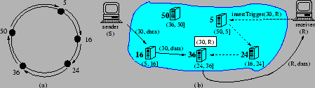
the identifier circle. Figure 2(a) shows an
identifier circle for
on
the identifier circle. Figure 2(a) shows an
identifier circle for ![]() . There are five
. There are five ![]() servers in the
system with identifiers 5, 16, 24, 36, and 50, respectively. All
identifiers in the range (5, 16] are mapped on server 16, identifiers
in (17, 24] are mapped on server 24, and so on.
servers in the
system with identifiers 5, 16, 24, 36, and 50, respectively. All
identifiers in the range (5, 16] are mapped on server 16, identifiers
in (17, 24] are mapped on server 24, and so on.
When a trigger ![]() is inserted, it is stored at the
is inserted, it is stored at the ![]() node
responsible for
node
responsible for ![]() . When a packet is sent to
. When a packet is sent to ![]() , it is routed by
, it is routed by
![]() to the node responsible for its
to the node responsible for its ![]() ; there it is matched against
(any) triggers for that
; there it is matched against
(any) triggers for that ![]() and forwarded (using IP) to all hosts
interested in packets sent to that identifier. Chord ensures that the
server responsible for an identifier is found after visiting at most
and forwarded (using IP) to all hosts
interested in packets sent to that identifier. Chord ensures that the
server responsible for an identifier is found after visiting at most
![]() other
other ![]() servers irrespective of the starting server (
servers irrespective of the starting server (![]() represents the total number of servers in the system). To achieve
this, Chord requires each node to maintain only
represents the total number of servers in the system). To achieve
this, Chord requires each node to maintain only ![]() routing
state. Chord allows servers to leave and join dynamically, and it is
highly robust against failures. For more details refer
to [25]. Figure 2(b) shows an
example in which trigger
routing
state. Chord allows servers to leave and join dynamically, and it is
highly robust against failures. For more details refer
to [25]. Figure 2(b) shows an
example in which trigger ![]() is inserted at node 36 (i.e., the
node that maps
is inserted at node 36 (i.e., the
node that maps ![]() , and thus is responsible for identifier
30). Packet
, and thus is responsible for identifier
30). Packet ![]() is forwarded to server 30, matched against
trigger
is forwarded to server 30, matched against
trigger ![]() , and then forwarded via IP to
, and then forwarded via IP to ![]() .
.
Note that packets are not stored in ![]() ; they are only forwarded.
End hosts must periodically refresh their triggers in
; they are only forwarded.
End hosts must periodically refresh their triggers in ![]() .
Hosts need only know one
.
Hosts need only know one ![]() node to use the
node to use the ![]() infrastructure.
This can be done through a static configuration file, or by a DNS lookup
assuming
infrastructure.
This can be done through a static configuration file, or by a DNS lookup
assuming ![]() is associated with a DNS domain name. In
Figure 2(b), the sender knows only server 16, and
the receiver knows only server 5.
is associated with a DNS domain name. In
Figure 2(b), the sender knows only server 16, and
the receiver knows only server 5.