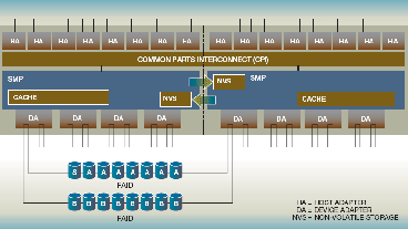
Figure 5 outlines the architecture of Shark. The architecture can support upto 16 host adapters (HA) in four host adapter bays. The host adapters can have fiber channel, ESCON, or SCSI ports. Shark has two active cluster processors with symmetrical multiprocessors (SMP) for performance, reliability, and availability. Each host adapter is connected to both the SMP clusters via the Common Parts Interconnect (CPI). Either cluster is able to handle IOs from any host adapter. Both the clusters have multiple SMPs in processor drawers and have an I/O drawer which provide PCI connections for access to non-volatile, battery-backed memory (denoted as NVS in the figure) and the device adapters (denoted as DA in the figure). The processor drawer also contains up to 32GB cache per cluster. For read data, the host adapter directs the request to the appropriate cluster. For write data, the data is written to both the clusters: on one it resides in the SMP RAM and on the other cluster it resides in the NVS memory. At the back-end, Shark uses RAID arrays (or arrays) that can be configured as RAID-5 or RAID-10. For further details on Shark, please see [31,39].