Kevin Lahey, Robert Braden
Information Sciences Institute, University of Southern California
Keith Sklower
University of California, Berkeley
A major class of network emulation testbeds is based on the Utah Emulab design: a local cluster of experimental nodes interconnected through Ethernet switches using VLANs. The VLANs are configured dynamically to create multiple concurrent experimental topologies. This cluster architecture allows deterministic testbed operation and therefore repeatable experiments. This paper explores the inter-experiment isolation problem for such testbeds, and in particular how to make the isolation robust against attacks when the testbed is designed to support the most dangerous cyber security experiments.
Each experimental node has multiple Ethernet interfaces, which are interconnected through a large Ethernet switch. Using Virtual LAN (VLAN) technology, this switch is configured dynamically by the testbed control software to create nearly-arbitrary network topologies among the nodes allocated to a particular experiment.
A key objective of cluster testbeds is to support repeatable experiments through deterministic operation, while cyber security testbeds are designed to support risky experiments. The DETER testbed [1] at USC/ISI and UC Berkeley is an example of a cyber security testbed. The architectural extensions discussed in this paper have been applied in DETER, but the design principles are not specific to DETER. Both determinism and safety require effective isolation among the inter-node links configured at any one time. The VLAN hardware support in the switch is the basic mechanism to provide this isolation.
This paper is concerned with a more particular problem in testbed architecture: experiment isolation that is fully robust in a cyber security testbed, in which an experiment might try to break out of isolation and attack other experiments or even the testbed control hardware. We will describe a modification to the basic Utah architecture to provide robust isolation even in the presence of insider attacks, i.e., attacks initiated by experiments with knowledge of the structure of the testbed. In practice, such attacks are much more likely to originate in experimenter errors rather than in experimenter misbehavior, but we are motivated to explore the limits to testbed containment of malicious programs.
An experimenter can load arbitrary code into assigned nodes and has root access. Hence, an experimental node can masquerade as any other experimental node in the testbed by changing its own IP and/or MAC address. This requires that experiment isolation be implemented at layer 2 of the protocol stack, the lowest layer accessible to the node programs. This is achieved by the use of VLANs and switched Ethernet connectivity.
The rest of this section abstracts those aspects of cyber security cluster testbed architecture that are relevant to isolation. It also summarizes the VLAN mechanism. Section 2 discusses the general isolation problem and various security threats posed by a lack of complete and robust isolation. Section 3 presents our solution to the architectural aspects of the isolation problem. Section 4 briefly discusses other possible approaches to experiment isolation. Sections 5 and 6 contain acknowledgments and conclusions.
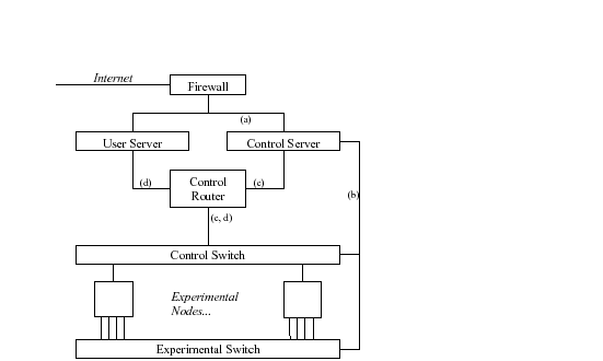
Figure 1 shows an abstraction of the architecture of a cyber security testbed like DETER. User Server and Control Server are two functionally-distinct server machines (and given the current implementation, the need to protect the testbed from hostile takeover by malicious users requires that they be separate platforms).1 The Control Server controls and monitors testbed operation. The User Server has login accounts and data storage for individual users.
Each experimental node has a small number N of Ethernet interfaces (typically 4 to 6). N-1 interfaces are used for experimental links, while the remaining control interface is reserved for accessing the node during an experiment, without perturbing the experimental traffic. 2 The Control Server also uses the control interfaces to boot, configure, and monitor experiments. All the interfaces of all the nodes could be wired to one big switch. However, it is easier conceptually to divide the switch into a Control Switch for the control interfaces and an Experimental Switch for the N-1 experimental interfaces on each node. Ports on both switches are configured dynamically by the Control Server, which knows the VLAN numbers and MAC addresses of each node interface. It creates links on the Experimental Switch to establish the topology requested by the experimenter.
The control interfaces are all connected to the control router through a subnet that we call the control network, regardless of how it is subdivided into VLANs. The control router runs layer 3 packet filters to block improper accesses to the Users or Control Servers.
In summary, the labeled links in Figure 1 have the following functions.
The Control Server may use link (c) to monitor and control the experiment, via a supervisory process planted in each node. The actual implementation of a cyber security testbed like DETER would include intrusion detection and firewall boxes that are not shown in Figure 1.
Since VLANs are central to experiment isolation, this section contains a brief summary of VLAN operation. VLANs operate at layer 2 of the stack to allow multiple independent Ethernet broadcast domains to coexist on a set of switches.
VLANs are identified by number, and each switch port may be configured with one or more VLAN numbers (see Table 1); we say that the port ``belongs'' to these VLAN(s). Ethernet packets outside the switch may be tagged with 12-bit VLAN numbers in an extension header whose format is defined by IEEE 802.1Q [5], or they may be untagged. DETER's switches are configured so that tagged packet entering a port must match one of the port's VLANs, or it will be dropped. Untagged packets entering the switch are implicitly tagged with the VLAN number of the entry port. A packet entering a port with multiple VLAN numbers (see port 4 in Table 1) will receive a default VLAN number, called the Port VLAN IDentifier (PVID).
In any case, the switch will assign a VLAN number to every incoming packet, whether tagged or untagged, and the packet can then be forwarded out all ports belonging to the same VLAN. A broadcast packet will be delivered to all such ports, while a unicast packet will exit through the port with a matching destination MAC address as well as VLAN number. In Table 1, VLAN 501 defines a connection between ports 1, 2, and 4, while VLAN 503 defines a hub connecting ports 3, 4, and 5. An untagged packet entering through port 4 will be implicitly tagged with the PVID (501) and sent to whichever of ports 1 and 2 has a matching MAC address, or to both 1 and 2 if its destination MAC address is an Ethernet broadcast address.
A switch port may be trunked, meaning that every outgoing packet will carry the 802.1Q VLAN tag. Trunking provides a mechanism for creating VLANs that span multiple switches. However, experimental nodes usually send and receive untagged packets on all their interfaces.
|
The architecture of Figure 1 blocks attacks on the Internet from experimental nodes (``extrusion''), since there is no direct IP path to the Internet. A conventional firewall prevents intrusion. Layer 3 packet filters on the Control Router limit the traffic between experimental nodes and the Control Server, allowing only what is needed for testbed operation and monitoring.
Our testbed architectural problem now becomes: how to provide complete isolation of each individual experiment, so it cannot attack or be attacked by another experiment.
The VLAN switch architecture described earlier provides complete logical isolation among the links forming the topology of an experiment, assuming that the switch hardware does not fail and that the Control Server that configures the switch is not compromised.
However, there is still a possible threat to isolation in the experimental topology: if the switch is not adequately provisioned, the traffic from one experiment may cause performance degradation in its own or other experiments' links. Ideally, the aggregate switch throughput should match all links being driven at the highest possible rate. (Note that what is possible may well be constrained by the nodes, not the links). Very high capacity switches are available (but expensive), but with current technology, at least, this performance interference cannot be totally avoided in reality. Measurements on particular switch hardware at DETER have shown that performance can vary in non-intuitive ways among the ports on a single switch based on traffic patterns. [6] We have extended the DETER testbed to detect traffic exceeding switch capacity and report it to users.
Per-experiment isolation on the control network is the central security problem that remains. There would be a number of possible sources of interference between experiments through a common control network.
Each node can send and receive using any IP address, so it can accidentally or deliberately send packets to nodes of another experiment, or masquerade to the testbed infrastructure as nodes in another experiment. Such an attack could be direct, or it could be a reflection attack - for instance, spoofing the source IP address to elicit ICMP error messages from testbed infrastructure, which could leak traffic into other experiments. A malware experiment might discover a control interface and start port scanning all of the experiments on the testbed, for example, or infect other experiments. Finally, the use of multicast for loading experiments might allow one experiment to interfere with the loading of another, e.g., by injecting malicious code.
Control network traffic from one network may create non-deterministic performance degradation for other experiments, but this should not be a threat to the repeatability of an experiment, since experimental traffic should never flow over the control network. [2] On the other hand, the OS on a testbed node does not generally make a clear distinction between its control network interface and its experimental network interfaces. It is quite possible for a careless experimenter to accidentally send experimental traffic over the control net. The testbed traffic monitors should be able to detect such a situation, if such mis-routed traffic is significant.
If there is a common control network, the use of multicast for downloading code and data into experimental nodes potentially exposes information to other experiments. Broadcast and multicast packets on the control network should be visible only to nodes in the relevant experiment. [2]
Other users (e.g., commercial users) may be concerned about privacy of their operating system images in the testbed. The current image distribution system uses multicast to send images to multiple nodes simultaneously, which exposes that information to all of the current users on the testbed. Per-experiment isolation of the control network could solve this problem as well.
The following types of packet traffic uses the control network legitimately. Any mechanism for creating per-experiment control subnets must support these traffic streams between each experiment and the User and Control Servers.
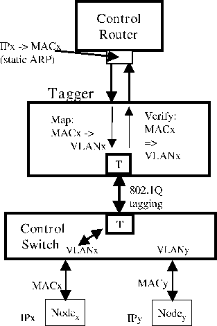
We now describe a layer 2 mechanism that will provide the required per-experiment isolation on the control network. This mechanism uses a new layer 2 box that we call the Tagger, deployed between the Control Router and the Control Switch (Figure 2).
The Tagger can sort packets, based on their MAC addresses, into a separate control VLAN for each experiment. The number of isolated experiments is limited only by the number of possible VLANs (usually 4094), not by the number of physical ports on any box. The Control Router continues to do all level 3 routing, while the Tagger effectively performs level 2 label switching.We describe the Tagger as a separate box for clarity of exposition, but in fact its function could be subsumed into the Control Router. This device is invisible to the users (and to the rest of the infrastructure).
Referring to Figure 2, the Control Router forwards packets from either
server to the Tagger. The router may use ARP to dynamically to map the destination IP address, ![]() , to the corresponding node
MAC address
, to the corresponding node
MAC address ![]() . In fact, using ARP is dangerous; a
malevolent node could use proxy ARP to subvert the packets of other
experiments. We therefore let the Control Server statically configure
the mapping table from destination
. In fact, using ARP is dangerous; a
malevolent node could use proxy ARP to subvert the packets of other
experiments. We therefore let the Control Server statically configure
the mapping table from destination ![]() address to
address to ![]() .
.
The Tagger performs the next stage in mapping. It contains a table
that is built and maintained by the Control Server, mapping ![]() to the corresponding VLAN number
to the corresponding VLAN number ![]() . The Tagger then forwards
the tagged packet out a trunk port to the Control Switch. The
control switch finally forwards the packet to the port for
. The Tagger then forwards
the tagged packet out a trunk port to the Control Switch. The
control switch finally forwards the packet to the port for
![]() and belonging to
and belonging to ![]() . A distinct
. A distinct ![]() is assigned
to all the ports of a single experiment.
is assigned
to all the ports of a single experiment.
A node in another experiment (e.g., ![]() in Figure 2) can fake its own
IP and MAC addresses. However, it cannot inject traffic into
in Figure 2) can fake its own
IP and MAC addresses. However, it cannot inject traffic into ![]() or
extract traffic from
or
extract traffic from ![]() , because of the fixed VLAN tag for each
experiment.
, because of the fixed VLAN tag for each
experiment. ![]() in Figure 2 is common to all nodes of one experiment
but it differs from the
in Figure 2 is common to all nodes of one experiment
but it differs from the ![]() of another experiment. Each control
VLAN is associated with a set of nodes; no other nodes can communicate
directly with that set of nodes.
of another experiment. Each control
VLAN is associated with a set of nodes; no other nodes can communicate
directly with that set of nodes.
When a node sends a packet on its control interface, the Control Switch
tags the packet with the VLAN number of the port on which it arrived at
the switch. The Tagger then uses its same mapping table to verify that
the packet's source MAC address matches the VLAN number it finds in the
tagged packet. Again, it will be impossible for ![]() to masquerade as
a node in another experiment (hence, with a different VLAN number).
As an additional precaution, the Tagger could
also ensure that the IP source address of the packet from an
experimental node matches the VLAN number.
to masquerade as
a node in another experiment (hence, with a different VLAN number).
As an additional precaution, the Tagger could
also ensure that the IP source address of the packet from an
experimental node matches the VLAN number.
Finally, the Control Router, operating at Layer 3, must not route back to the Tagger packets that arrived from the Tagger; this can be accomplished using small enhancements to the current firewall rules on the Control Router.
We turn now to multicast, which is important for efficient loading of experiment images. The Control Server might send images using a NACK-based reliable multicast scheme.4 [4] This implies that the receiving nodes would multicast NACKs that should be received by both the Control Server and the other nodes in the same experiment that are loading the same image. This is trivial if there is a single common control network for all experiments. We need to preserve this general capability with the Tagger box.
For efficiency, we perfer to do the replication of multicast packets as close to the experimental nodes as possible; this would be the Control Switch (see Figure 2).
The Control Server may send out several concurrent streams of multicast packets, each stream for downloading one OS image, with a distinct per-stream IP multicast destination address in each packet and a corresponding multicast MAC address (the IP multicast addresses used by the Control Server are chosen to fall into the range of allowable multicast MAC addresses). When the packet arrives at the Tagger, the multicast MAC address will cause the Tagger to map:
MAC -> (VLAN1, VLAN2, ...),where MAC is a multicast Ethernet MAC address. The list of target VLANs allows multiple experiments to receive the same stream when desired and no privacy concerns are present. The Tagger replicates the packet if necessary to forward one copy, tagged with each VLAN in the list, to the Control Switch. The Control Switch will broadcast the packet to all interfaces for each experiment in the list.
The testbed control software must be extended to automatically configure the Tagger with the appropriate MAC address and VLAN information for both unicast and multicast addresses.
Unicast addresses are relatively straightforward to configure; the testbed has already compiled a list of per-node MAC addresses, and merely changes the MAC to VLAN mappings as required when a node moves from one experiment to another. Of course, the testbed software has a variety of ways to move nodes between experiments, requiring careful placement of new code for each of these ways.
Multicast mappings are more complex, and change more frequently. Every time a node loads a new image, the testbed must ensure that it gets the appropriate multicast packets, and, once the load is complete, must remove the multicast mapping.
A daemon is spawned for each image to be loaded; this daemon chooses multicast addresses and ensures that the multicast distribution servers are running. The daemon is modified to update the tagger with new multicast address mappings whenever a node requests an image. If a node in the same experiment is already using that image, obviously, no change need be made.
Similarly, a testbed daemon tracks changes to nodes. When a node which was previously reloading enters a new state, the daemon can check to see if that node was the last one in an experiment requesting that image. If so, the multicast MAC mapping to that experiment can be removed.
Before arriving at the Tagger mechanism described in Section 3, we considered several other approaches to provide per-experiment isolation on the control network.
The Emulab software allows an experiment to assign one of its allocated nodes to act as a per-experiment firewall. Then all other control interfaces in the experiment will be assigned a newly-generated VLAN number, attached to that firewall node. The firewall is intended to protect the experiment from other traffic on the control network, while it forwards multicast and other testbed infrastructure traffic from the regular control net VLAN to the firewalled VLAN.
However, this mechanism would provide only a partial solution to the general isolation problem. Unfortunately, the user can log into the firewall and manipulate the configuration. To achieve the level of protection provided by the Tagger, we would have to force all experiments to use the per-experiment firewall feature, and somehow prevent the user from logging into the firewall. This universal deployment would require an extra node dedicated for each experiment on the testbed.
Some vendors have extended their switch architecture to provide groups of ports, or communities, that can communicate only among themselves or with a ``promiscuous'' port. [3] The control interfaces of each experiment could be a community, while the Control Router would attach to the promiscuous port. Then the nodes within the experiment would be able to communicate (only) between their own community (experiment), and with the router. This scheme has been called Private VLANs (PVLANs).
Using PVLANs for experiment isolation, if they were universally and reliably available, would avoid the addition of the Tagger box. It would require only reconfiguration of the switches for each new experiment, in addition to changing the Control Router to ensure that it doesn't route packets back into the PVLAN.
Unfortunately, current implementations do not fully meet the requirements set forth in this paper. In particular, it appears to be impossible to restrict multicast distribution to selected PVLANs.
The Tagger concept was originated by Nick Weaver. He suggested a Click-based device to sort packets into the appropriate VLANs and to verify that incoming packets are coming from appropriate VLANs, distinct from the router.
Ted Faber and other members of the DETER staff, along with the CSET reviewers, provided invaluable feedback.
This material is based upon work supported by the Department of Homeland Security, and Space and Naval Warfare Systems Center, San Diego, under Contract No. N66001-07-C-2001.
Any opinions, findings and conclusions or recommendations expressed in this material are those of the authors and do not necessarily reflect the views of the Department of Homeland Security for the Space and Naval Warfare Systems Center, San Diego.
We have described the security and integrity threats raised when a secure cluster testbed uses a single common control network VLAN, and presented a general layer 2 isolation mechanism to meet those threats. The threats include experimental malware attacking not only the testbed infrastructure but also other experiments, which are considerably less hardened. Since some experimenters may intentionally run insecure images as part of their research, there is an urgent need to provide robust isolation between experiments on the control network.
This document was generated using the LaTeX2HTML translator Version 2002-2-1 (1.70)
Copyright © 1993, 1994, 1995, 1996,
Nikos Drakos,
Computer Based Learning Unit, University of Leeds.
Copyright © 1997, 1998, 1999,
Ross Moore,
Mathematics Department, Macquarie University, Sydney.
The command line arguments were:
latex2html -split 0 -show_section_numbers -local_icons -no_navigation lahey_html
The translation was initiated by Kevin Lahey on 2008-07-15