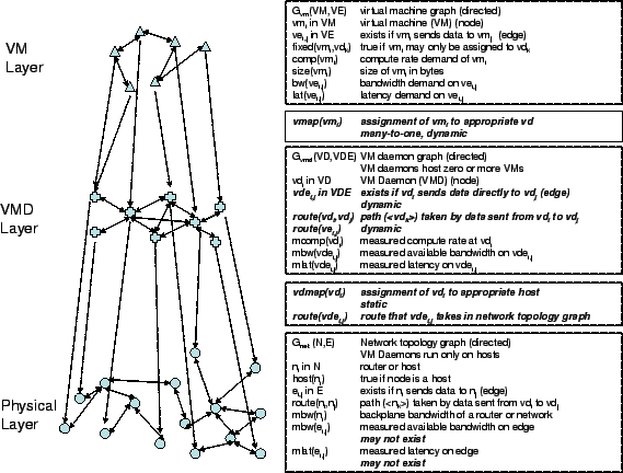
Figure 7 serves as a point of reference for the terminology we use in describing our design and the problems it induces. On the left hand side, we can see the three layers: the virtual machines themselves (VM layer), the virtual machine daemons that host them (VMD layer), and the physical network resources on which the VMDs run (Physical layer). The graph of VM Daemons is the overlay itself. A VM daemon or VMD is a generalization of a VNET server that is able to manage VMs and measure their traffic and the characteristics of the underlying network. The nodes and edges at the VM layer are mapped to nodes and routes at the VMD layer. The physical layer is the underlying IP network itself. The nodes of the VMD layer are mapped to the end-systems of this network. The right hand side of Figure 7 shows the symbols we use at each layer and the mapping between layers. The boldfaced symbols represent where adaptation and the use of underlying resource mechanisms can take place.
The VM layer consists of the individual VMs (![]() ) and the
communication edges among them (
) and the
communication edges among them (
![]() ), represented as a
graph (
), represented as a
graph (![]() ). If
). If ![]() sends to
sends to ![]() , then there is an
edge
, then there is an
edge ![]() in
in ![]() . The VM layer is essentially a representation
of the demands that the user's VMs are placing on the system.
. The VM layer is essentially a representation
of the demands that the user's VMs are placing on the system.
![]() and
and ![]() are the bandwidth and latency
requirements of communication between
are the bandwidth and latency
requirements of communication between ![]() and
and ![]() .
. ![]() is the computational demand of
is the computational demand of ![]() , while
, while ![]() is the total
size of its machine image.
is the total
size of its machine image.
The VMD layer consists of VM daemons (![]() ), and the
communication edges among them (
), and the
communication edges among them (
![]() ), represented as a
graph (
), represented as a
graph (
![]() ). If
). If ![]() sends to
sends to ![]() , there must be a
route (
, there must be a
route (
![]() ) between them. A virtual machine
) between them. A virtual machine ![]() is
assigned to a single VMD (
is
assigned to a single VMD (![]() ). Hence, an edge
). Hence, an edge ![]() in
the VM layer corresponds to a route
in
the VM layer corresponds to a route
![]() in the VMD layer.
Multiple VMs may be assigned to a single VMD. At the VMD layer, we
also maintain the measured bandwidth and latency of edges in the
in the VMD layer.
Multiple VMs may be assigned to a single VMD. At the VMD layer, we
also maintain the measured bandwidth and latency of edges in the
![]() ,
,
![]() ,
,
![]() , and the computational
rate at each node (
, and the computational
rate at each node (![]() ).
).
The physical layer consists of the underlying topology,
![]() , where the nodes
, where the nodes ![]() are the routers and hosts
at the IP layer and
are the routers and hosts
at the IP layer and ![]() are the links.
are the links.
![]() are the routes chosen by the network, and
are the routes chosen by the network, and ![]() is true if
is true if
![]() is a host. In addition, we may be able to measure the
bandwidth and latency of the elements of a link (
is a host. In addition, we may be able to measure the
bandwidth and latency of the elements of a link (![]() ,
,
![]() ), the backplane bandwidth of a router (
), the backplane bandwidth of a router (![]() ), and
the raw computational power of a host (
), and
the raw computational power of a host (![]() ). Each VMD is
assigned to a single host in the physical layer, and each host has at
most a single VMD. This mapping is via
). Each VMD is
assigned to a single host in the physical layer, and each host has at
most a single VMD. This mapping is via ![]() . Each edge in
the
. Each edge in
the ![]() turns into a route
turns into a route
![]() at the physical
layer.
at the physical
layer.