Check out the new USENIX Web site. Previous Up Next

4  Analysis of Class I Memorable Password Space

To contribute towards a security evaluation of DAS, we determine the size of the more probable subsets of the DAS Class I memorable password space (recall §3), i.e. the number of DAS password encodings (see §4.1) representing at least one memorable password (recall §3). This is based on the reasoning that the number of entries in a ``successful" attack dictionary provides a measure of security.

The DAS graphical password scheme relies on a user's ability to recall their DAS password ``exactly" (as defined by the resolution of the encoding scheme). What users must recall can be divided into two parts: the temporal order of the strokes used in making the drawing, and the final appearance of the drawing. The latter is what our Class I memorable passwords capture, as it appeals to people's ability to recall images. Assumptions concerning the temporal order (i.e. the order of the input of cells) are made in §4.2 and §4.3 to perform this analysis, leading us to define a set S.

§4.2 discusses our terminology and general approach. §4.3 discusses additional cases. §4.4 discusses variations of the attack dictionary. §4.5 briefly discusses our resulting method to quantify the DAS memorable password space. §4.6 presents some computational results.

4.1  Review of DAS Scheme

The DAS scheme [11, 16] decouples the position of the input from the temporal order, producing a larger password space than textual password schemes with keyboard input (where the order in which characters are typed predetermines their position).

A DAS password is a simple picture drawn on a G × G grid. Each grid cell is denoted by two-dimensional coordinates (x, y) ∈ [1 … G] × [1 … G]. A completed drawing is encoded as a sequence of coordinate pairs by listing the cells through which the drawing passes, in the order in which it passes through them. Each time the pen is lifted from the grid surface, this ``pen-up" event is represented by the distinguished coordinate pair (G+1, G+1). Two drawings having the same encoding (i.e. crossing the same sequence of grid cells with pen-up events in the same places in the sequence) are considered equivalent. Drawings are divided into equivalence classes in this manner.

DAS disallows passwords considered difficult to repeat exactly (e.g. passwords involving pieces lying close to a grid boundary). The definition of ``close to a grid boundary" is unclear [11]; we define it as any part of a stroke that is indiscernible as to which cell it lies within, meaning it lies within the fuzzy boundary of a grid line. Any stroke is invalid if it starts or ends on a fuzzy boundary, or if it crosses through the fuzzy boundary near the intersection of grid lines. We reuse the following terminology. Jermyn et al. [11] recursively compute the (full) password space size, i.e. the number of distinct representations of graphical passwords in the DAS scheme. This gives an upper bound on the memorable password space and thus on the security of the scheme. It is assumed that all passwords of total length greater than some fixed value have probability zero. They compute the full password space size for passwords of total length at most Lmax. For Lmax =12 and a 5 × 5 grid, this is 258, exceeding the number of textual passwords of 8 characters or less constructed from the printable ASCII codes (the sum from i= 1 to 8 of 95i is less than 253).

4.2   Basic Terminology and General Approach

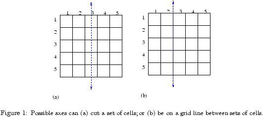
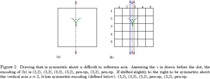
To capture visually mirror symmetric DAS passwords, we first consider which reflection axes to use. We assume that the user references the grid lines for the symmetry in the drawing, since if the reflection axis is a point of reference, the password will be easier to repeat exactly. Therefore, the reflection axes considered are those that cut a set of grid cells (Fig. 1a), or are on a grid line (Fig. 1b). This means that any symmetric password drawn such that its axis is off-center within a set of cells is not considered. For example, the password in Fig. 2a is visually symmetric when the grid is not in place, but we do not consider it part of the DAS Class I set of memorable passwords since its reflection axis is not on a grid line or centered in a set of cells as shown in Fig. 2b. We justify this assumption as follows: it is more difficult for a user to draw an exactly repeatable symmetric password without a visible point of reference on the grid for the reflection axis.


We thus define the set of axes within a W × H grid (width W, height H): A = AhAv ; Ah = {1, 1.5, 2, … , (H-1).5, H } ; Av = {1, 1.5, 2, … , (W-1).5, W } . Here i.5 is the grid line separating rows i and i+1, or columns i and i+1 respectively.


In addition to the visual appearance of a DAS password, the most likely ways in which a visually mirror symmetric DAS password can be drawn must be considered in constructing a DAS Class I graphical dictionary. It turns out to be quite tricky to map the idea of a visually mirror symmetric DAS password onto DAS encodings to enumerate, as we describe in a number of cases (below and in §4.3). DAS Class I memorable passwords are only defined in terms of their visual structure. There is a one-to-many relationship between a given Class I memorable password to the number of ways it can be drawn in the DAS scheme (which are then mapped to possibly less unique DAS encodings). We believe there are some more likely ways that users will draw mirror symmetric components in their DAS passwords; we call this ``more probable" subset of unique DAS encodings S.

Preliminary user studies have shown that the temporal order has an adverse effect on user's ability to recall a DAS password [8]. If the temporal order is a complicating factor that adds more complexity to what users must recall, it is likely that they will choose DAS passwords with less complexity (e.g. less strokes). We assume the way users will draw a DAS Class I password is such that the composite stroke(s) of each mirror symmetric component are drawn in a symmetric manner (as defined in the disjoint case as described in this section and the continuous and enclosed cases as described in §4.3). We believe the resulting subset S captures the easiest (and thus more likely to be chosen) ways to draw DAS Class I memorable passwords.

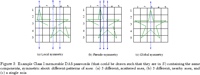
We model each symmetric DAS password as a series of strokes (each representing a single component or pair of components) that have local symmetry about a set of axes, each such stroke modeled by a virtual start point s and virtual end point e (not necessarily the start and end points of the user-drawn stroke). A stroke has local symmetry if it is symmetric about some axis in a given set of axes. This includes drawings where all or most strokes are symmetric about different axes, which may have no immediately perceivable pattern, as shown in the example password in Fig. 3a. When the strokes are symmetric about axes in the same vicinity, it results in an increasingly symmetric drawing as a whole, which we call pseudo-symmetry. An example of a pseudo-symmetric drawing is shown in Fig. 3b. When the strokes are all symmetric about the same axis, it results in a drawing that has global symmetry (e.g. the star in Fig. 3c); since all strokes are symmetric about the same axis, the entire drawing is symmetric about the same axis.


We define a symmetric encoding to be an encoding that represents an equivalence class of DAS passwords, where at least one password in the equivalence class belongs to S. Using the DAS encoding scheme, a symmetric encoding may represent a number of passwords, some of which may not be visually mirror symmetric (e.g. see Fig. 4).

Fig. 4 illustrates different representations of one equivalence class of DAS passwords with the same symmetric encoding. This implies our results count not only mirror symmetric passwords, but also others which are not but belong to an equivalence class in which at least one password is mirror symmetric.


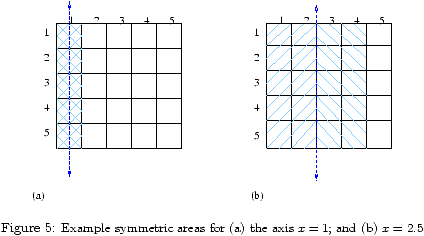
Each stroke within a symmetric encoding is bounded within a symmetric area, defined as the area between a given axis and the closest grid boundary parallel to the axis, reflected about the axis (see Fig. 5).


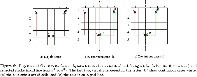
The most obvious way to draw a stroke in a symmetric manner is to draw a stroke within the symmetric area, then draw its reflection about the reflection axis as shown in Fig. 6a. We call the initial stroke from virtual start point s to virtual end point e that the reflection is based upon the defining stroke, and the reflection the reflected stroke, which can be drawn from sR (the reflection of s) to eR (the reflection of e) or vice versa.3

Given a defining stroke z, its reflected stroke zR (relative to an axis a) is said to be an exact reflection if zR is z's mirror image about a and they are separated by a pen-up. Exact reflection is not required to have a stroke that exhibits mirror symmetry (see §4.3). A symmetric stroke is the combined result of a defining stroke and a reflected stroke. A valid point, relative to an axis a, is any point that is contained within the symmetric area defined by a (see Fig. 5). A valid defining stroke, relative to an axis a, is a defining stroke consisting solely of valid points within the symmetric area defined by a. A valid symmetric stroke is the composition of a valid defining stroke and its reflected stroke. We define a valid symmetric stroke that holds the property of exact reflection to be the disjoint case. As a disjoint case has the property of exact reflection, its length will always be even.

The product of the number of ways to draw a defining stroke and the number of ways to draw its reflected stroke provides the number of ways to draw a symmetric stroke, excluding additional cases (§4.3 discusses the latter, namely the continuous case and the enclosed shape case).


4.3  Continuous and Enclosed Cases

A point in an encoded defining stroke is potentially continuous if it lies within a cell that is either cut by the reflection axis a in question, or adjacent to a when a is on a grid line. If a point p is potentially continuous, its reflection pR is in the same cell as p or in a neighbouring cell, and thus the stroke can be drawn directly from p to pR without a pen-up. When the start and end points of the defining stroke are potentially continuous, the three most straightforward ways to draw the resulting symmetric stroke are as follows: disjointly (the disjoint case -- recall §4.2), as one continuous stroke (the continuous case), or as one continuous enclosed stroke (the enclosed case).

A symmetric stroke can be drawn as a continuous case when the defining stroke's end point is potentially continuous. We define the continuous case as when the defining stroke continues through a to the reflected stroke, creating a single, continuous symmetric stroke. For example, the encoding for Fig. 6b would be: (1,1), (1,2), (1,3), (1,4), (2,4), (3,4), (4,4), (5,4), (5,3), (5,2), (5,1), ending with a pen-up. The stroke could also be drawn in the reverse order. Examples of the same visual representation of a `U', with one disjoint and the other continuous, are shown in Figures 6a and b. Note that the continuous case's encoding is different, depending on whether a cuts a set of cells or is on a grid line. If a cuts a set of cells as in Fig. 6b, the defining stroke's endpoint e is the same as its reflection eR. Since there is no pen-up to separate e from eR, it cannot appear in the encoding twice, thus eR does not appear in the resulting encoding. If a is on a grid line (Fig. 6c), e and eR reside in different cells, and eR does appear in the resulting encoding.

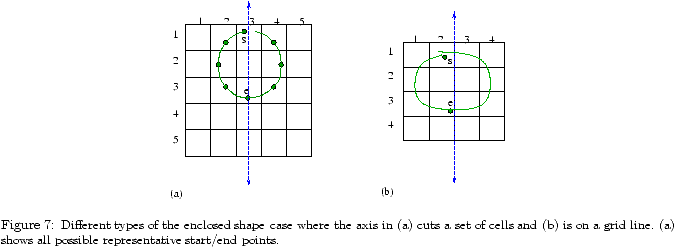
A symmetric stroke can be drawn as an enclosed case when both the defining stroke's start and end points are potentially continuous. We define the enclosed case to be when the defining stroke continues through a to the reflected stroke, and then joins back up with the defining stroke, creating an enclosed shape (e.g. Fig. 7). When a shape is enclosed, the drawing may start and end at any point in the shape and still retain its mirror symmetry. As with the continuous case, the enclosed case's encoding is different, depending on whether a cuts a set of cells or is on a grid line. The continuation of the defining stroke into the reflected stroke will be encoded as in the continuous case; the difference between these two cases is the encoding to join the reflected stroke back into the defining stroke. When a is on a grid line, the start point of the defining stroke is repeated as the last point of the user's stroke (e.g. Fig. 7b). When a cuts a set of cells (e.g. Fig. 7a), it is the same as the continuous case since s = sR, enclosing the shape. Thus, to avoid double-counting, we exclude from the continuous case, the cases where s is potentially continuous.


4.4  Smaller Graphical Dictionaries

It is in an attacker's best interest to reduce the graphical dictionary size to decrease the attack time and increase probability of success relative to the effort expended. A logical way to attempt to do so is to assume that it is more likely for a user to choose the center-most axes as the reflection axes. We define Class Ia as those passwords in Class I whose components (recall §3) are symmetric (in their own right, or pairwise) about the center 3 of each set of axes (i.e. the marked axes in Fig. 8). This produces pseudo-symmetric drawings (recall §4.2, Fig. 3b). This optimization of the graphical dictionary reduces its size as a function of the grid size. We also define Class Ib as those in Class I whose components are symmetric about the center vertical and horizontal axes. This produces drawings with global symmetry. The Class Ib dictionary is a subset of the Class Ia dictionary, which is a subset of the Class I dictionary.


If pseudo-symmetry is considered more likely than global symmetry, the attacker may choose to use those passwords that are composed of strokes symmetric about a small set of close axes, such as Class Ia. The size of the dictionary will increase exponentially with each additional axis considered, meaning that the time to exhaust the dictionary is reduced by this method, particularly with higher values of Lmax. Class Ib captures all passwords that are globally symmetric and centered about the grid (vertically and/or horizontally), plus those that have components symmetric about the center vertical and horizontal axes (e.g. the coffee cup in Fig. 9). If the user subconsciously uses the grid to frame the drawing (i.e. using the grid as part of the drawing's overall symmetry), the resulting drawings would be globally symmetric about either of the center axes.


4.5  Quantifying the Memorable Password Space

Our general approach to quantify |S| (recall §4.2) is to determine how many DAS passwords in S are of length at most a given maximum password length Lmax. The composite strokes of each password in S have defining strokes that connect a given virtual start and end point in the symmetric area. Counting all passwords of length at most Lmax and defining passwords in terms of strokes follows Jermyn et al. [11]; however, our method for defining the set of strokes of a given length is entirely different, and only symmetric strokes are included in the set.

The key points of our method of quantifying |S| are discussed in this section (for more details see [25]). Generally, the base formula for defining the set of strokes does the following: for every possible virtual start point s=(x,y), and end point e=(x,y) in a given W × H grid, we determine the number of ways to draw a symmetric stroke (symmetric about any valid axis in A) of length l based on a defining stroke that joins s to e. The reason for specifying s and e is so we know explicitly whether s and/or e are potentially continuous (recall §4.3) in order to enumerate the continuous and enclosed cases.

The number of defining strokes from s to e is enumerated by examining the number of permutations of up, down, left, and right movements that join s to e while remaining within the bounds of the symmetric area, for all valid axes in A. The primary considerations in this method are: path diversions, and the amount of room between the current position and the bounds in every direction within a given symmetric area.

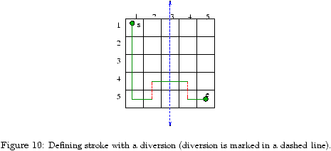
The number of possible diversions for a given s, e, l, and axis aA is based on the difference between the desired defining stroke length l/2 and the minimum length path (stroke with the least number of cells) that joins s to e. The difference between l/2 and the minimum length path required to join s to e is the number of extra cells that should exist in the stroke from s to e that divert from the minimum length path. In order for the defining stroke with diversions to connect s to e, each diversion must be paired with a cell crossing in the opposite direction to reconnect with the minimum length path. An example of a diversion is provided in Fig. 10.


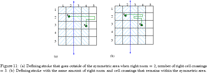
Room is the number of cell crossings in a given direction that can occur from s, before the defining stroke goes out of the symmetric area bounds in question. If at any point in the defining stroke, the number of left cell crossings exceeds the number of right cell crossings by more than the amount of left room, the defining stroke is invalid. The use of room in other directions is analogously defined. Given a starting point s and the symmetric area, we know the amount of available room in each direction. For example, in Fig. 11, right room = 2, left room = 1, top room = 1, and bottom room = 3.


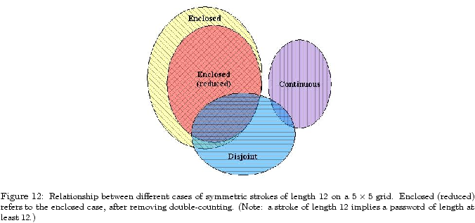
When l is even, the symmetric strokes enumerated for a given s and e are a combination of the disjoint, continuous, and enclosed cases. When l is odd, the symmetric strokes enumerated for a given s and e are a combination of the continuous and enclosed cases. These sets intersect due to the nature of our counting method. In determining the size of an overall memorable password space, overlaps must be accounted for to avoid double-counting. Fig. 12 gives a representative illustration of how the strokes intersect with one another when l is even (more specifically, l = 12); when l is odd, the disjoint case is void (recall §4.2).

If a symmetric stroke z has a symmetric defining stroke zD, and a symmetric reflected stroke zR, z is the same as two independent symmetric strokes, which can be independently included in S (i.e. they are either continuous symmetric strokes or enclosed symmetric strokes). Thus, we must ensure that all disjoint case symmetric strokes that have symmetric defining strokes are subtracted from the count.


Some enclosed shapes will be double-counted by this method since an enclosed stroke may be symmetric about both a horizontal axis aAh and a vertical axis aAv (e.g. Fig. 13). The double counting is due to counting all possible start/end points of an enclosed shape case. The enclosed shapes that are symmetric about an aAh and an aAv can be identified as those whose defining strokes are symmetric. We identify and subtract those defining strokes that are symmetric continuous cases (including those whose start point is potentially continuous). This involves determining the candidate axis ac and all candidate mid-points m that will produce a continuous symmetric stroke from s to e. These defining strokes must be identified only once; we identify them when aAh. In Fig. 13, the symmetric defining stroke (about the horizontal axis) is indicated as the circular dashed line.


We are aware of other smaller cases of overlap that we have experimentally determined as insignificant to the overall results. One such case is when the reflected stroke is identical regardless of whether it is drawn from sR to eR or from eR to sR, but is not an enclosed case (e.g. lines that repeat over each other more than once). Additionally, there is a smaller set of defining strokes that result in the same symmetric stroke when reflected about one horizontal and another vertical axis, which occurs when the second half of the defining stroke is a 180 degree rotation of the first half of the stroke. There may be other small cases of overlap that we are presently unaware of, but we believe that the set we used will account for any overlap of significant impact on the overall result.

4.6  Approximate Size of Class I Memorable Password Space

Table 1 gives sample results computed using the method outlined in §4.5 (for details including equations, see [25]) for S (recall §4.2) and the intersection of S with Class Ia and Class Ib memorable passwords (recall §4.4), respectively denoted SIa and SIb. Values given are log2(number of passwords). SIa and SIb both show an exponential reduction from the full DAS space: SIb grows at an exponential rate of approximately 3.6 bits per unit increase in password length and SIa grows at a corresponding rate of approximately 4.0, whereas the full DAS space and S grow at a corresponding rate of approximately 4.8. The size of the full DAS password space was double-checked using a variation of our method, and essentially agrees with the results given in [11].

Lmax 1 2 3 4 5 6 7 8 9 10
Full DAS space 4.7 9.5 14.3 19.2 24.0 28.8 33.6 38.4 43.2 48.1
(i) S 4.7 9.5 14.3 19.1 23.9 28.7 33.6 38.4 43.2 48.0
(ii) SIa 3.3 7.7 11.6 15.7 19.8 23.8 27.9 31.9 36.0 40.0
(iii) SIb 3.3 6.9 10.5 14.1 17.7 21.2 24.8 28.4 32.0 35.6
Lmax 11 12 13 14 15 16 17 18 19 20
Full DAS space 52.9 57.7 62.5 67.3 72.2 77.0 81.8 86.6 91.4 96.2
(i) S 52.8 57.6 62.4 67.2 72.0 76.8 81.7 86.5 91.3 96.1
(ii) SIa 44.1 48.1 52.1 56.2 60.2 64.3 68.3 72.4 76.4 80.4
(iii) SIb 39.1 42.7 46.3 49.9 53.4 57.0 60.6 64.2 67.8 71.4

Table 1: Bit-size of graphical password space, for total length at most Lmax on a 5 × 5 grid.


Each of the three subclasses of Class I memorable passwords presented in Table 1 allow perceptually quite distinct classes of drawings (recall Fig. 3 and §4.4). We found the size of S to be surprisingly close to that of the full DAS space; however, upon reflection this is sensible, as the only requirement for a stroke to be symmetric is that it is locally symmetric about any axis in A (e.g. Fig. 3a), which includes the combinatorially large set of all permutations of dots and lines of length two.

The smaller the set of axes used, the smaller the graphical dictionary becomes. It is a reasonable strategy for an attacker to narrow down the graphical dictionary to a small number of axes, or at least prioritize a search such that globally symmetric passwords (e.g. Fig. 3c) are considered first. When a single axis (or two) are considered at a time to produce globally symmetric passwords, each result will never be larger than that for the two center axes, as the latter maximizes the symmetric area in which the passwords can reside. Thus, the maximum dictionary size of such a variation would be at most a small constant factor, proportional to the number of axes considered, of that using only the center axes. We believe that the set of globally symmetric passwords best captures the symmetry discussed in §3, and our intuition suggests that Class Ib (e.g. Fig. 3c) is more likely than Class Ia (e.g. Fig. 3b), which is more likely than Class I (e.g. Fig. 3a).

To provide context for the practical implications of our results, we discuss how long it might take to perform a dictionary attack against the DAS scheme using each of the above graphical dictionaries. The exact method used to perform a dictionary attack depends on the authentication method used by the system. We assume that authentication is performed by hashing the entered password using the MD5 hash algorithm, then comparing the hashed password to the password file entry for the user.4 In this case, a dictionary attack requires comparing the hashed value of each candidate password to the hashed value of the target password, hoping for a match. Here the attack time is at least the time to hash each candidate password. Thus, we tabulate the time required to hash all passwords in each password set for comparison.

We calculate two sets of times: one where we assume the attacker has one Pentium 4 3.2GHz machine, and another where we assume the attacker has one thousand such machines, with which linear speed-up is achieved. It is reasonable to consider that a determined attacker could exploit one thousand, or even one hundred thousand machines using a worm, to distribute the password-cracking load. Using an MD5 performance result of 3.66 cycles/byte for a Pentium 3 800MHz machine [10] (scaled to 3.2GHz), and a 512 bit block size, approximately 1.37 × 10⁷ hashes can be performed per second per machine. Given the assumed resources, the estimated time to generate the password hashes is given in Table 2.

Dictionary Time to exhaust Time to exhaust
(Lmax=12) (1 machine) (1000 machines)
Full DAS Space 541.8 years 197.8 days
S 505.6 years 184.5 days
SIa 255 days 6.1 hours
SIb 6 days 8.7 minutes

Table 2: Time to exhaust various dictionaries (3.2GHz machines, 5 × 5 grid).


The times provided in Table 2 highlight the implications of the graphical dictionary size. Assuming that we want an attacker to require an average of 10 years to exhaust these dictionaries with 1000 computers at 3.2GHz, the dictionary size must be approximately 263. Referring to Table 1, our Class Ib dictionary (global symmetry) is above this size when Lmax = 18. This implies that for this level of security (and a 5 × 5 grid), DAS users should choose passwords of length at least 18.

Note that an attacker may achieve success substantially faster than the times given in Table 2 if dictionary entries are ordered according to their probability of occurring. For example, if the entire Class I password dictionary was used, it would be reasonable to order it such that all those that also fall into Class Ib are first, followed by those remaining that fall into Class Ia, etc. Note that if the target passwords are not in any of the above dictionaries, the attack will fail.

Some of the larger textual password dictionaries contain approximately 4 × 10⁷ entries [19]. Our smallest graphical dictionary exceeds this number of entries for Lmax ≥ 8. This implies that even if users choose the globally mirror symmetric passwords we have defined, provided the password length is at least 8, the DAS scheme may still offer greater security than textual passwords against dictionary attacks.


Previous Up Next