|
USENIX 2003 Annual Technical Conference, FREENIX Track — Paper
[USENIX Annual Conference '03 Tech Program Index]
| Pp. 245-258 of the Proceedings | |
Free Software and High-Power Rocketry:
The Portland State Aerospace Society
James Perkins Andrew Greenberg
Jamey Sharp David Cassard Bart Massey
Portland State Aerospace Society
Computer Science Department
Portland State University
Portland, OR USA 97207--0751
james@psas.pdx.edu andrew@psas.pdx.edu
jamey@cs.pdx.edu dcassard@psas.pdx.edu bart@cs.pdx.edu
http://psas.pdx.edu
Abstract
The Portland State Aerospace Society (PSAS) is a small, low-budget
amateur aerospace group. PSAS is currently developing medium-sized
sub-orbital rockets with the eventual goal of inserting nanosatellites
(satellites that weigh less than 10 kg) into orbit. Because achieving
orbit requires a navigation system able to guide the rocket along an
orbital trajectory, PSAS is pioneering an open source and open
hardware avionics system that is capable of active guidance.
In this paper, we describe how free software and open hardware have
dramatically changed the capabilities of amateur aerospace groups
like PSAS. We show how we have applied existing and custom free
software to the avionics and ground support systems of a sub-orbital
sounding rocket, and discuss what further work must be done.
We conclude that the sophistication and complexity achieved by current
amateur avionics projects---which are beginning to challenge the
distinction between amateur and professional---would not be
possible without the use of free software.
1 Overview
This paper details the role of free software and open hardware in our
group, the Portland State Aerospace Society (PSAS). First we introduce
the field of rocketry, and how PSAS is making contributions to
the field. This is followed by a history of the group's rocket
development and an overview of our current project. We then cover the
details of our system, including requirements, flight software,
ground software, and the project management and
collaboration tools. Finally, we discuss our future work, and draw
conclusions about the applicability of free software to projects
like ours.
2 Introduction to Rocketry
Rocketry has a rich history of significant contributions made by amateur
groups. Indeed, most national space programs can trace their roots back
to small, active groups of amateurs working on rocketry during the early
part of the 20th century [Win83].
Amateur rocket motor classifications are categorized by their total
impulse, which is total force multiplied by burn time. ``A'' motors have
up to 2.5 Newton-seconds (Ns) of total impulse, and each successive
letter of the alphabet doubles the impulse range of the previous
letter [Tri].
Today, rocketry includes a wide spectrum of participants and can
generally be divided into four categories.
Model rocketry involves the smallest and most common types of
rockets, with motors made of pressed black powder that are smaller than
320 Ns (``H''), and bodies built out of balsa wood and cardboard or
phenolic (resin) tubes. Most model rockets weigh less than a kilogram
and are recovered with a small parachute or streamer.
Since model rockets generally stay below 460 m (1,500 ft), they avoid
most government regulation in the US.
Hobby rocketry begins from the upper limits of model
rocketry. Motors delivering up to about 10,240 Ns (``M'')
of thrust are common. Motors are typically made of
composite fuel (ammonium perchlorate in a HTPB plastic
binder), and are sometimes clustered or staged to achieve
greater power. Some high-powered hobby rockets can reach
more than 6 km (20,000 ft), so launches in the US
are government regulated and require launch waivers. Most
hobby rockets use commercially available, single board
avionics systems that sense the best time to eject
parachutes [alt], although some
custom-built avionics packages have been much more
sophisticated.
Amateur rocketry usually implies a certain level of innovation
and customization, such as custom motors, custom avionics and metal airframes.
This innovation may be inspired by a lack of suitable commercial
solutions or a desire to ``do it yourself''. The current altitude record
for an amateur group is 85 km (280,000 ft) with a 327,680 Ns (``R'')
motor [rrs].
Professional rocketry is the most familiar category. It
includes organizations such as NASA and the European Space Agency (ESA),
along with their private contractors such as Lockheed Martin, Boeing,
and Orbital Sciences.
Over time, the line between amateur and professional rocketry has
blurred. Some industry observers discriminate by financial gains, technical
expertise, or sheer altitude achieved, but there is no common standard.
Indeed, as technologies such as computational power and integrated
sensors become cheaper and more available, the capabilities of amateur
groups have begun to catch up to some professional projects.
3 The Portland State Aerospace Society
The Portland State Aerospace Society (PSAS) was founded in 1997 by two
students at Portland State University (PSU) in Portland, Oregon to
provide an aerospace-based, systems-level educational design project.
PSAS has launched one hobby and two high-powered amateur rockets.
The group has grown to include more than three dozen people, including
high school, undergraduate and
graduate students, as well as engineers from local industry. Current PSAS
projects are focused on taking small, manageable steps towards the the
distant vision of inserting nanosatellites (satellites that weigh
less than 10 kg) into orbit.
Is it possible for amateur rocketry groups to achieve orbit? None have, to date.
In most countries, the regulatory hurdles are at least as much of a challenge for an
amateur group as the substantial technological and financial issues.
The US Commercial Space Launch Act of
1984 requires any rocket with over 890,000 Ns (``S'') of impulse lasting
for 15 seconds or more to meet stringent safety requirements set by the
FAA, NASA, and Commercial Space Transportation Board
(CSTB) [csl, sls].
These requirements include an extensive safety analysis, which can take
years and cost hundreds of thousands of dollars.
Furthermore, vehicles which actually achieve orbit must comply with
international ``space law'' as laid out in various international
agreements [un].
While fulfilling the goal of achieving
orbit may be beyond the ability of our
small group, the enabling technologies needed to get there by an amateur
group are now readily obtainable: inexpensive computational power, sophisticated
sensors, high-power actuators, and the availability of robust, open
source software for engineering and logistical support.
3.1 Toward Amateur Active Guidance
To achieve orbit at minimum cost, a rocket must follow an ``orbital
trajectory'' that minimizes both the aerodynamic drag in the lower
atmosphere and the time to get to orbit [Wer92].
To follow such a trajectory, the rocket must be able to measure
its current trajectory, compare against the planned trajectory, and
actively correct for errors. This ability to follow a trajectory is
called ``active guidance'', and the authors know of no amateur
group that has yet achieved this. To bridge this gap
in amateur rocketry technology, PSAS has chosen to work on open
source and open hardware high-powered amateur rockets that are capable
of active guidance.
There are many meanings of active guidance. Here we use active guidance
in the classic rocket sense: a guidance computer on-board the rocket measures the
rocket's current position, heading and course. The guidance
computer
then activates a
steering mechanism in order to guide the rocket along a predetermined
path.
To determine the rocket's position, attitude (orientation) and
trajectory (flight path), a rocket's flight computer uses data from
one or more sensors:
-
GPS receivers provide absolute position at a slow (~1 Hz) rate.
- Inertial Measurement Units (IMUs) provide relative linear and
rotational acceleration, velocity and position using accelerometers and
gyroscopes at a faster rate (~1 kHz).
- Magnetometers provide attitude (orientation) by comparing the
local magnetic field to a 3D map of the Earth's magnetic field.
- Pressure sensors allow altitude to be computed from atmospheric
pressure models.
- Optical sensors, such as star and horizon trackers, may be used to
compute attitude.
Each of these sensors have different signal and noise
characteristics.
Kalman filtering [CC99] is a signal processing algorithm
for combining noisy sensor data that provides guarantees on
the optimality of its estimate. This estimate can then
be used as an approximation of the rocket's true position, attitude
and trajectory.
To steer the rocket, some mechanism must apply a force to the rocket
during flight. Steering mechanisms vary widely:
-
Small fins are common, but are ineffective above about 25 km
(82,000 ft).
- Reaction Control Systems use small rocket motors to adjust the
heading of the rocket, but are usually large, heavy systems
that are
ineffective in the lower atmosphere.
- Thrust Vector Control changes the angle of the main motor's
thrust, for example by gimballing the main motor nozzle, by independently
throttling multiple clustered motors, by putting small movable vanes in the
path of the exhaust, or by injecting extra oxidizer into the
edge of a fuel-rich
exhaust stream [SB00].
To ``close the loop'', estimates of position, attitude and
trajectory are used to calculate steering commands. The most difficult
part of active guidance may be getting the signal processing in the
control loop correct. Many famous rocket failures, such as the first
launch of Ariane 5, were due to simple errors in design
or implementation of the navigation system
algorithms [ins].
3.2 Related Work
Many amateur groups exist today, but none that the authors know of
are currently working on active guidance. Guided amateur designs do
exist, but all either track the sun or are used to simply
stabilize the rocket in flight. None can actually be used to follow
a planned trajectory. An excellent example of a guided, but not actively
guided, rocket is the MARS Rocket Society's gyroscope-controlled
gimballed-nozzle rocket [mar].
3.3 Launch Vehicles
Because we strongly emphasize safety, reliability and new functionality
for every launch, PSAS has launched only four times over its six year
history. In a field with failure rates as high as 30% at some events,
we have not yet lost a vehicle. Further, each new launch has demonstrated
new airframe or avionics functionality which justified the time and
expense of performing a launch.
Table 1: Comparison of PSAS Launch Vehicles
| Name |
Size |
Dia. |
Weight |
Ns |
Altitude |
Cost |
Design |
CPU |
OS |
|
| LV0 |
1.8 m |
10.0 cm |
5.4 kg |
J |
0.3 km |
$500 |
4 mo. |
PIC16C |
Interrupt-driven |
| LV1 |
3.4 m |
11.0 cm |
19.5 kg |
M |
3.6 km |
$2000 |
18 mo. |
PIC17C |
Interrupt framework |
| LV2 |
4.0 m |
13.6 cm |
46.0 kg |
P |
23.0 km |
$10000 |
>21 mo. |
5x86 |
Linux / RTLinux |
3.3.1 Launch Vehicle No. 0
The first PSAS project began with four volunteers and a simple hobby
rocket dubbed ``Launch Vehicle No. 0'' (LV0). The team modified a
commercial kit of cardboard tubes and balsa wood with fiberglass and
epoxy resin and added a simple avionics system.
While the airframe took only a weekend to complete, the avionics system
took two people a few months of building and testing. The avionics
system had just a few components: a 1 MHz 8 bit RISC microcontroller;
a micro-electro-mechanical (MEMs) accelerometer;
a 426 MHz 1 W amateur television (ATV) transmitter;
a monochrome video camera; and a commercial logging altimeter.
The interrupt-driven microcontroller firmware was written in assembly
language. Accelerometer samples were downlinked using the ATV audio channel
at 300 bps. Telemetry data was then logged on a 386 DOS laptop.
LV0 was launched on June 7, 1998 (Table 1).
Not surprisingly, things went wrong. The airframe was all
but unstable and a short circuit in the wiring harness erased system
memory. However, the received images and data proved the
soundness of the overall system concept.
3.3.2 Launch Vehicle No. 1
LV0's success attracted more volunteers: about a dozen people designed
and built the next generation rocket, Launch Vehicle No. 1 (LV1). The
airframe was made of carbon fiber over a PVC and aluminum core, and was
built by one person over 3 months, with little engineering analysis.
The LV1 avionics system was arguably the most advanced
amateur rocket avionics package in the world in 1999. Its subsystems included:
-
A custom flight computer board with an 8 bit 33 MHz RISC
microcontroller, 1 MB of non-volatile SRAM for data logging,
pyrotechnic ignition circuitry, and interface circuitry to
other subsystems including temperature and pressure sensors.
- An inertial measurement unit (IMU): X, Y, and Z axis linear
accelerometers and yaw, pitch, and roll rate gyroscopes. These sensors
produced a ``six degree of freedom'' measurement which was
numerically integrated to calculate the rocket's 3D position and velocity.
- A commercial 12-channel GPS receiver.
- A color video camera and microphone that transmitted over a 426 MHz ATV
transmitter.
- A 913 MHz 1 W transmitter that sent 19.2 kbps telemetry data encoded by
the flight computer.
- A 146.43 MHz (2 m) amateur radio receiver with a DTMF decoder.
Decoded tones were sent to an independent microcontroller
that could fire the
recovery system or send commands to the flight computer
in an emergency.
The flight computer's assembly-language, interrupt-driven executive
sampled all sensors, logged data, and transmitted low-pass filtered
telemetry. The firmware also used the GPS, IMU and pressure sensors to
determine the rocket's altitude and thus when to deploy the recovery
system.
LV1 required extensive ground support due to its size and complexity. A
surplus pneumatic lifter was modified into a launch tower with a 6 m
(20 ft) launch rail. Launch control software automatically performed the
countdown and launched the rocket via a 903 MHz wireless link
to a small microcontroller-run relay board.
Another Linux-based ground computer captured, logged and displayed
live telemetry data with a custom GTK-based application. This
helped the range safety officer decide if the flight was proceeding as
planned: if not, the emergency radio could be used to deploy the
recovery system (parachutes) even if the flight computer failed.
LV1 was launched on April 11, 1999 and again (as LV1b) on October 7,
2000 (Table 1). Half of the $2,000 development cost
came from an IEEE/AT&T ``Student Enterprise'' grant.
LV1's complexity led the dozen-plus volunteers to divide into airframe,
avionics and logistics teams. Each team had their own mailing list, web
page and FTP folders. However, formal design methods were mostly
ignored and the web site was updated infrequently. Designs were
implemented without review, which caused schedule slips and and two
``scrubbed'' launches.
3.3.3 Launch Vehicle No. 2
The next generation launch vehicle needed the flexibility, modularity
and extensibility that LV1 lacked. A few of the lessons learned include:
-
Real-time Operating Systems (RTOS's) hand-built in assembly language
are not a good idea for a complex, multi-volunteer effort. An
off-the-shelf RTOS with better networking and free, easily learned
development tools is much more appropriate.
- The navigation software needs serious computational power:
a CPU with hardware floating point support is highly desirable.
- Subsystems in the avionics system must be easily added, removed
or swapped.
- The airframe itself must be flexible and expandable to
handle unforeseen requirements.
The design of LV2 took more than a year of careful coordination between
the avionics and airframe teams. The
design process was much more formal than had
previously been tried. A white paper was written on the various design options
for the avionics system. The airframe team used finite-element analysis
to predict the performance of different airframe structures. To fund
the project, PSAS applied for and won the 2000 Oregon Space Grant,
a $10,000 NASA-sponsored small grant program.
The LV2 airframe uses a flexible and modular design to facilitate swapping
out entire subsystems such as the avionics, recovery or propulsion
(motor) unit. We have also separated the
avionics system from the payload module, enabling LV2 to fly other
academic or amateur rocketry payloads. The resulting airframe
is made of cylindrical aluminum modules covered by a fiberglass aeroshell.
Simulations predict a maximum altitude of 23 km (75,000 ft)
(Table 1).
Based on a computational complexity analysis of the navigation software,
we decided to use a flight computer with a floating point unit (FPU),
better support for multitasking, and a modern development toolchain.
However, a single-processor avionics system was unappealing because of
the high-rate, I/O-intensive tasks many of the sensors
required:
controlling a high speed analog-to-digital converter and
running a closed loop motor controller, for example.
A multi-node common bus solves many of these problems by enabling a larger,
more powerful central flight computer to communicate with many smaller
microcontrollers. This allows a ``smart
sensor'' and ``smart actuator'' approach that frees up the central
processor to perform higher-level calculations and
supervisory tasks.
We chose the Controller Area Network (CAN) bus as our intra-rocket
multi-node bus. The CAN bus is an automotive bus developed
by Robert Bosch, GmbH which is quickly gaining acceptance in both the industrial
and aerospace markets. CAN is a multi-master, losslessly-arbitrated
serial bus that can be run up to 1 Mbps. The CAN bus includes
packet-level checksums and tolerance of node
errors (including logic that forces a node off of the bus if it
is causing errors). Perhaps the most interesting aspect of CAN is its
message-based identification of packets: instead of node addresses, the
CAN bus identifies and prioritizes the messages based on an 11 bit
identifier. Each message, such as GPS location, or IMU inertial data,
is broadcast on the bus with a unique message ID [can].
For the central flight computer we have selected the PC104
form-factor. This allows us to use standard off-the-shelf
parts instead of taking the time and effort to make our
own. The flight computer consists of:
-
A Jumptec MOPS520 PC104+ board, a 133 MHz 5x86 processor (the AMD SC520)
with 64 MB of SDRAM, typical PC ports, and a CAN interface.
- A carrier board for a 128 MB CompactFlash hard disk.
- A PCMCIA carrier board for a Lucent Orinoco 802.11b card.
Considerable
difficulty was encountered in developing the wireless telemetry system for
LV1. We thus wanted a commercially available long-range
high-speed bi-directional wireless telemetry system for LV2:
such a system could be used for telemetry
as well as by the rocket, launch tower and ground
computers. After some research, we gravitated toward the Amateur Radio
Relay League (ARRL) 802.11b standard. ARRL
802.11b is the IEEE 802.11b 2.4 GHz spread spectrum standard, but
operated under the FCC amateur radio regulations (FCC Part 97) instead of
the low-power, unlicensed regulations of the 2.4 GHz ISM band (FCC Part
15). Running under ARRL 802.11b allows us to use up to 100 W of radiated
power. Our current system uses a standard PC-Card (Lucent Orinoco), a
1 W bidirectional power amplifier, and high gain (+12 dB) helical ground
antennas [arr].
The smaller sensor/actuator CAN nodes use the Microchip PIC18F458, an
8 bit, 40 MHz RISC flash-memory microcontroller with a built-in CAN protocol
unit. There are currently five CAN nodes:
-
The LV1 IMU.
- A SigTech Navigation MG5001 OEM GPS receiver.
- A power interface node to control system power and track battery
charge.
- A recovery node---a battery-backed up CAN node with high voltage
pyrotechnic firing circuitry. Like LV1, it has a 2 m amateur radio
receiver which decodes DTMF tone sequences sent as emergency commands.
- An ATV node, consisting of a color video camera, ATV transmitter, power
amplifier and an overlay board that displays textual vehicle
status information along
with NTSC flight video.
The CAN nodes have proven to be useful general-purpose
building blocks: new nodes are frequently
prototyped atop a generic ``misc CAN node'' design.
4 Software Overview
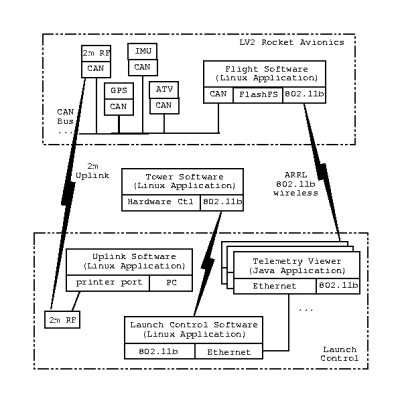
Figure 1: LV2 System Software
The software system is divided into three major areas:
-
Flight Software
-
Flight Computer Software flies in the rocket, and runs on a
single-board computer running Debian GNU/Linux
(Section 5.1).
- Avionics Firmware flies in the rocket, and runs on multiple
independent microcontroller nodes (Sections 5.2--5.3).
- Ground Software
-
Launch Control Software is used by the
flight control officer
to sequence the rocket launch. Launch Tower Software
manages launch tower electronics (Section 6.1).
- Telemetry Display Software is used by the flight
control officer and
spectators to view the rocket's status.
(Section 6.2).
- Uplink Software is operated by the range safety officer at
launch control and sends emergency commands through the 2 m uplink
(Section 6.3).
- Collaboration Software runs on the (Portland State
University) hosted PSAS server.
The PSAS server is the locus for a variety of services
including mailing lists, collaborative web
pages and CVS repositories (Section 7).
4.1 Functional Requirements
There are a number of mandatory requirements for a successful
rocket launch. In order of priority:
-
Safety. The risk of death, injury, and property
damage must be minimized
- Reliable Recovery. The airframe
must be safely recovered. The principal software constraint
is to deploy the recovery
parachute only at apogee, when vertical airspeed is at a minimum.
- Flight Data Recovery. The purpose of every flight is to
collect new data: data recovery is thus essential.
- Telemetry Downlink. Real time sensor data must be
easily monitored by the launch controller to decide whether or not to
override the flight computer via the emergency uplink.
- Radio Dropout Tolerance. Radio links are notoriously
unreliable. The software must be able to tolerate link failures.
- Recovery Assistance. Position information must be
available to the recovery teams tracking the rocket after the parachutes
have opened. High winds or malfunction can carry the rocket
kilometers away during ascent or
descent.
- Power Management. Intelligent power management is
crucial to reliable performance. Power use also constrains
peak altitude. Lithium batteries store energy at a density of
~300 WHr/kg. Thus,
during a
standard flight profile each watt used on the rocket adds 30 g
(1.1 oz) of battery weight. Simulations predict that the altitude-
to-weight ratio is -335 m/kg. Thus every watt used on the rocket
means a reduction of 10 m (33 ft) of altitude.
4.2 Logistical Requirements
The volunteer nature of our group imposes some special
project management requirements:
-
Minimize Coordination Overhead. In our
project, collaboration is entirely ad-hoc. Project synchronization and access
control mechanisms must reflect this.
- Minimize Training. Well-known development methods
are necessary to enable immediate contributions
by our new volunteers.
- Limit Costs. Funding is scarce: we must take advantage
of any available cost reductions.
4.3 Choosing a Common Platform
Our requirements for a low-cost, reliable and flexible platform
discourage the use of non-free, proprietary and unfixable software
and suggest using well-documented, open-standards-based
free software. GNU/Linux not only runs on the limited
hardware we have available, but also enables the use of thousands of
free software applications available for UNIX environments.
We have standardized on the Debian GNU/Linux distribution for all of our
development, collaboration and rocket systems in order
to reduce the amount of time spent maintaining and installing
software [deb].
Thanks to Debian's Advanced Package Tool (apt),
our systems generally require little maintenance effort
while remaining relatively secure.
This enables us to focus on our development efforts
instead of struggling with platform and tool configuration. It also
reduces the time necessary to configure development environments for our
new volunteers.
4.4 From Soft to Hard Real-time
The term ``real-time'' refers to applications that require guaranteed
bounds on the time between the occurrence of an event and the software's
response. Soft real-time requirements allow for occasional missed
deadlines under high load, but hard real-time applications must meet all
deadlines under all conditions [Lab99].
Linux is designed to optimize throughput, not to guarantee
hard real-time
response. Processing may be delayed by mutexes,
interrupt locks, high interrupt load, paging, and other causes. The
scheduling latency of a Linux task may be improved using the
sched_setscheduler() system call to identify it as a ``real-time''
task. Other tricks include using mlock() or mlockall() to avoid paging delays, and enabling
full kernel preemption using various kernel patches [Gal95].
While these approaches improve mean response time, the
system
delays are still unbounded.
One approach to regions of code requiring hard
real-time response is to move them below the user API into or below the
kernel,
where the code paths and potential interruptions to them can be fully
understood. For example, interrupt handlers might be used to schedule
Linux kernel threads, limiting code analysis to the interrupt handler
path.
For full control over response time, the entire flight computer
application could be run on a hard real-time operating
system. There are several light-weight commercial
offerings, such as Wind River's VxWorks operating
system, the QNX Microkernel and Jean Labrosse's
MicroC/OS-II. However, commercial RTOS's
generally require specialized programming knowledge, often support
a narrower array of devices than free software, and can
be expensive.
Fortunately, the best of both worlds may be found in real-time operating
systems that run the entire Linux kernel and all user processes in the
lowest-priority thread. One such offering is FSMLabs
Inc.'s RTLinux [fsm].
The hard real-time elements of our software can be implemented using the
real-time kernel primitives: everything else runs as Linux user
processes.
The PSAS flight computer application has a variety of requirements.
Some components have no real-time requirement, while others have soft or hard
real-time requirements. For the next launch, our application's real-time
requirements are soft: launch and apogee must be detected and handled
within a second, and data must be logged and transmitted to the
ground as soon as possible. However, the introduction of navigation
algorithms on future launches will require us to move to hard real-time,
and we plan to begin using RTLinux with our Fall 2003 launch.
5 Flight Software
Table 2: Processors used in the LV2 Avionics System
| System Name |
Arch. |
Bits |
Speed |
RAM |
Flash |
MMU? |
OS |
|
| Flight Computer |
AMD 5x86 |
32 |
133 MHz |
64,000 KB |
128,000 KB |
Y |
Linux |
| GPS Receiver |
ARM7TDMI |
32 |
40 MHz |
128 KB |
1,000 KB |
N |
eCos |
| CAN Nodes |
PIC18 |
8 |
40 MHz |
2 KB |
32 KB |
N |
PicCore |
The LV2 flight system uses three significantly different
kinds of processors (Table 2). This
necessitates three significantly different software
architectures: processes running in a 32 bit pre-emptive
multitasking RTOS; threads running in a light-weight
POSIX-compatible RTOS; and tasks running in a custom
interrupt-driven framework. In this section we review these
software architectures. Note that we distinguish firmware
from software: firmware consists of small, hardware-oriented
programs stored in nonvolatile memory and considered read-only by
the local processor.
5.1 Flight Computer Software
A key element of the application software running on the
5x86-based flight computer (see
Section 3.3.3) is its message-passing
architecture. This software is currently written in C, and
runs in a Debian GNU/Linux environment with a Linux 2.4
kernel. Messages are passed across the wireless link,
across the CAN bus and to the nonvolatile data log
(Figure 1).
Every component of the PSAS avionics system has different response speed and latency
characteristics. In order to avoid holding up the whole application,
each device is monitored and controlled by one or more
asynchronous execution tasks. Coordination of these tasks is
accomplished by passing messages between them, initially by using a
message server task.
We have been through three flight computer software designs
with
different message-handling schemes: ``Muxer'',
``Renegade'' and ``FCFIFO''.
After introducing these designs, we will discuss some other
flight-computer software elements of interest: the CAN Bus driver and
our network configuration.
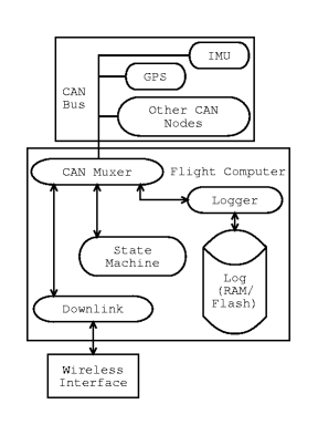
Figure 2: Muxer Flight Computer Software Design
The first design was implemented in C using POSIX threads, TCP/IP
sockets, and device I/O processes. The processes passed messages by
connecting to a server process called Muxer, which broadcasted
each message received to every other task.
Muxer's server thread began by
initializing a shared buffer. It then
listened for TCP/IP connections. The central data structure was a
variable-sized shared queue of messages. When a client connection was
accepted, the server thread spawned client queue reader
and writer threads. The new client's queue reader thread slept, waiting for new
messages to arrive in the queue. The client's queue writer waited for an
incoming message and enqueued it. Queue access was serialized by a
mutex, and semaphores were used to wake sleeping queue
readers when
new messages were waiting for delivery. The last client to read a
message from the queue deallocated that queue element.
The Muxer design included a client library to ease creating a TCP/IP
connection to the Muxer service. Clients were mostly other Linux
processes on-board the flight computer or (via the wireless link) on the
ground (Figure 2).
A shell script first started the Muxer server process, then each of
the client processes.
The client processes would open and initialize their I/O device.
They would then use the Muxer client library to open a connection to the Muxer
server thread.
There were some difficulties with this design:
-
Excessive wake-ups. The star message topology with N clients
resulted in each new message waking up N threads, which wrote N messages
to the network stack, which woke up N processes to read the data.
- Message synchronization. Messages were of variable size, making
mid-reception synchronization to a message stream a challenge.
- Debugging. Debugging POSIX threads was
difficult. Threads would sometimes damage the environment
of their neighbors.
- Opacity. The queue structure, its mutex and use was not easily understood
by the team.
- Wrong protocol. TCP/IP was a poor choice for
wireless communications, incurring multi-megabyte
queuing and retries in the network layer. Ultimately a downlink process
was added to bridge the messages into a UDP protocol for the wireless downlink.
A CAN bus reader was implemented and Muxer was demonstrated to
work. Nonetheless, when changes were introduced that broke
Muxer,
no one was able
to find the time to sort out why. Team members eventually realized
that solving the flight computer design problem by starting from the
message handling structure and then moving out from there was not
working.
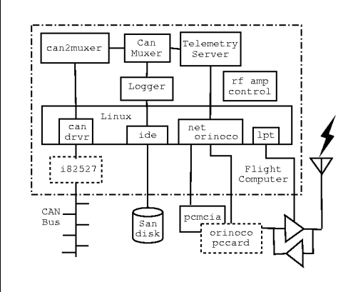
Figure 3: Renegade Flight Computer Software
Design
One team member began working on an independent effort, and titled it
the ``Renegade'' design. Renegade continued the theme of a central
Muxer task dispatching each message to all asynchronous I/O-handling
clients. However, the architecture
was implemented as a UNIX process with UNIX pipes to
child I/O processes (Figure 3).
The top-down, application-oriented and simplified design was an
improvement. Most importantly, needed rocket functionality was quickly
completed:
-
CAN bus messages were read and distributed
successfully to all I/O devices.
- Intertask communication became independent of networking.
- Wireless dropouts were handled efficiently rather than
causing backups.
- Fixed-sized messages eliminated synchronization issues.
- Debugging with GDB and UNIX signals was trivial.
- The Linux kernel design could be relied on for optimized
intertask performance.
Renegade did have shortcomings.
-
The lack
of message filtering and
the broadcast architecture still
led to excessive wake-ups.
- The inherited pipe structure made it difficult to restart I/O
processes from the shell.
- UNIX pipes were difficult to inject data into for testing
and debugging.
- No throughput tests were ever attempted.
After some consideration of Renegade's shortcomings, we once
again decided to redesign
the flight computer software to correct them.
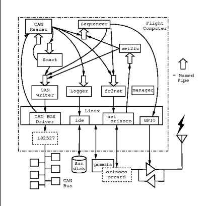
Figure 4: FCFIFO Flight Computer Software
Design
The third and completed design is called FCFIFO. It combines the
independent processes from the Muxer design with the conventional UNIX
interprocess communications of Renegade. In addition, it eliminates the
central multiplexer (Figure 4).
On startup, each process
opens a uniquely named pipe to read messages from, then opens
the named pipes of any processes it needs to communicate with. By
eliminating the central multiplexer, task switch and copying
overhead are minimized.
A simple Linux user-mode process-oriented application will satisfy the
June 2003 soft real-time requirements. While named pipes do not
guarantee a response time, they do aid in maximizing throughput.
They also allow processes to run asynchronously, because
they can
buffer a
few messages if the reading process falls behind. As components
transition to RTLinux hard real-time tasks, this architecture will be
ideal: named pipes are the preferred means of communication between
Linux and RTLinux tasks.
Where it is advantageous for activities to occur independently, the
application implements these via separate processes.
-
Logger takes messages on its named pipe and stores them
in the nonvolatile log file.
- CAN Reader opens the CAN bus device and blocks until it
reads a message either from the CAN bus or from its named pipe. It
passes messages to the Logger and networking for storage, sensor
information to Smart, and a few other events to Sequencer.
- CAN Writer opens the CAN bus device for writing and waits
for incoming CAN messages on its named pipe. It then sends those
messages out onto the CAN bus.
- Fc2Net waits on its named pipe for a message, then
broadcasts the message to the wireless network using our UDP application
protocol.
- Net2Fc initializes a UDP server port, then waits for a
message. If a command comes from the ground via the wireless
network,
Net2FC
passes the command on to other relevant processes.
- Smart evaluates raw sensor data and converts it into a
more useful form. (We discovered that this is a difficult component to
name. After much thought, we decided it is the ``Smart Module Assembling
Real-time Tasks''.) For example, GPS and IMU data are
processed to obtain
position, velocity, and acceleration information. Smart also detects events such as
rocket launch, apogee, and touchdown.
- Sequencer decides when the system should transition
from one rocket flight state to another, and generates the commands
needed to set up the CAN nodes for the new state.
- Manager is analogous to the UNIX init process. It starts
the whole set of named pipe children, restarts children that die
unexpectedly, and manages a graceful application shutdown.
5.1.4 Linux CAN Bus Driver
CAN communication is performed through a GNU GPL
82527 CAN chip driver for Linux, written by Arnaud
Westenberg and adapted
to our the flight computer's 82527 interface [lcb].
The driver allows applications to communicate with the CAN bus through
the /dev/can0 device node.
5.1.5 Network Configuration
During development, the flight computer communicates with development
machines using its built-in Ethernet or local IEEE 802.11b wireless. In flight
configuration it uses the ARRL 802.11b hardware described in
Section 3.3.3. Standard Linux PCMCIA and Orinoco drivers
configure and integrate the network hardware.
However, a simple custom
driver is needed to switch the system between IEEE and ARRL 802.11b
modes: the 2.4 GHz bidirectional power amplifier can be turned on and
off via two general purpose I/O pins on the flight computer.
The wireless network card is configured to use channel zero (2.400 -
2.450 GHz, which is within the amateur 13 cm band), IBSS ad-hoc
networking mode, a fixed IP address from a private network address
range, and the maximum power output available from the card.
Enabling IBSS ad-hoc networking prevents the card from participating
in auto-configuration via a management device such as a wireless
access point. The telemetry viewing computers at launch
control are the only other device similarly configured, to limit
performance-robbing traffic collisions.
All network transmissions between the rocket and ground control use UDP
broadcast packets. This provides a low-overhead transmission path with
no packet retries. TCP was briefly considered for rocket communications,
but TCP requires a reasonably error-free communications medium. Given
the extreme 23 km distance of the rocket , antenna geometry effects, attenuation
due to the motor's exhaust plume, and tracking error of the ground
antennas, it cannot be assumed that the wireless link can support
TCP communications.
The telemetry and control protocol is symmetric, time-stamped, and is
logged on each end. This allows us to measure communications loss through
post-flight data analysis. Periodic general status messages from
the rocket allow the ground software to resynchronize key parameters
rapidly even when
communication is intermittent. A data payload checksum helps validate the
quality of the received data, although invalid data frames are also
logged to aid in link quality analysis.
5.2 CAN Node Firmware: ARM7TDMI
The Global Position System (GPS) receivers on-board LV2 are commercially
available boards that use the Zarlink GP4020 GPS correlator
chip [gpsb], a custom ASIC with a 12-channel correlator and an
ARM7TDMI microcontroller core. The receivers come with closed-source
proprietary firmware which runs the correlators, processes the satellite
data, and transmits position and velocity information over a standard
asynchronous serial bus.
Unfortunately, the navigation algorithms in commercially available GPS
receivers fail to cope with the high dynamics of LV2 and will lose
satellite lock when the vehicle exceeds 515 m/s, 18 km in altitude,
or 8 g's of acceleration. Because LV2 will exceed these limits and a
locked GPS receiver is a critical part of our navigation system, we have
started a separate project: developing free firmware for GPS receivers which
use the GP4020 chip. Dubbed GPL-GPS [gpsa], the firmware is
based on Clifford Kelley's ``OpenSource GPS''
project [kel] and will allow the receivers to stay locked
during highly dynamic flights. The open firmware will allow us to
implement our own sophisticated processing techniques,
including integrating the GPS and IMU into a GPS-aided inertial
navigation system [FB99]. The firmware may also allow us to:
-
Implement local differential GPS corrections via a similar GPS
receiver on the ground in a known, static position. Enabling a local
differential base station can yield positioning accuracies
in the 1 m range.
- Use multiple GPS
receivers to determine attitude (orientation) by comparing the
position of their antennas.
- Keep GPS lock on the satellites by integrating data from the inertial
measurement unit to aid the correlator tracking loops.
We chose to use an existing RTOS in order to speed up firmware
development, and because a multi-threading abstraction will simplify
the GPS firmware design. GPL-GPS requires an RTOS with extremely low
latency, POSIX compliance to facilitate porting, a reasonable free
or open-source license, ability to run in 1 MB of flash memory and 128 KB of
RAM, and a reasonable effort level (estimated as a time
multiplier) for us to implement with our
hardware.
Based on our research (Table 3), we selected Red Hat's eCos
(embedded Configurable Operating System) [Mas03] as the best fit to our
criteria. We are currently working on the alpha release of the GPL-GPS
project, which includes a port of eCos and Kelley's OpenSource GPS to
the GP4020. We hope to have initial results by September 2003.
Table 3: Embedded Operating Systems Comparison
| Name |
RT |
POSIX |
Free |
Small |
Effort |
|
| RTLinux |
Y |
Y |
Y |
N |
1x |
| µcLinux |
N |
Y |
Y |
N |
2x |
| MicroC/OS-II |
Y |
N |
N |
Y |
4x |
| µITRON |
Y |
N |
Y |
Y |
4x |
| eCos |
Y |
Y |
Y |
Y |
4x |
| Custom |
Y |
N |
Y |
Y |
10x |
5.3 CAN node Firmware: PIC18
The Microchip PIC18F458 8 bit RISC microcontrollers [pic] used on the CAN nodes
(see Section 3.3.3) have 1.5 KB of RAM, 32 KB of
flash memory. and a long list of peripherals. The latter
include an 8-channel 10 bit analog to digital converter,
various serial interfaces including CAN, timers and an in-circuit
debugging port. The PIC18 is used as a small and simple
interface between sensors and the CAN bus,
implementing a rudimentary ``intelligent sensor and actuator'' network.
Because of the extremely tight memory constraints and the simple
functionality of the firmware, we have written a custom C-language
interrupt-driven framework called ``PicCore''.
Unfortunately, there are few free software applications for PIC18
development. For example, there is no GCC cross-compiler for the PIC18
family. The GDB debugger does not support Microchip's ``ICD2'' in-circuit
debugging tool. Our current development environment consists of Microchip's
no-cost Windows-based integrated development
environment (MPLAB IDE) [pic], graciously donated copies of
HI-TECH Software's PICC-18 C compiler [C18], and Microchip's ICD2
debugger/programmer. Our failure to get MPLAB to run under emulators
such as WINE unfortunately require us to have Windows-based development
environments for the PIC18 developers. Developing our own PIC18
development tools would exceed the resources of our project, so for now
we have resigned ourselves to operate with two development environments.
We are currently searching for equivalent hardware that has better
free software development support.
6 Ground Systems
The software and hardware components on the ground (as shown in
Figure 1) have several objectives:
-
Maintain the safety of all participants and bystanders.
- Initiate the launch sequence (with means of emergency abort).
- Receive and record telemetry data from the vehicle during flight,
- Receive and record video broadcast from the vehicle during flight,
- Initiate manual recovery procedures if the flight software appears
to be failing.
Due to our small budget, our volunteer team has always relied on the
kindness of strangers for available computing hardware. As a result,
we need to be able to run our software on as many hardware and
software configurations as possible. We have chosen Java as our ground
systems language because Java byte-code enables us to run our code on
any sufficiently powerful platform. Java's automatic memory management
and simple GUI framework make ideal tools for user interfaces and
data visualization. Java is well known: many of the developers
in our group are familiar with it.
6.1 Launch Control Software
The launch control software is a Java application which steps through an
automated launch sequence. The sequence of events is coordinated with the
rocket and launch tower via ARRL 802.11b wireless links: the launch
tower may be several kilometers away from launch control for safety
reasons. Safety systems include manual interlocks and a
rocket-controlled interlock triggered on flight computer diagnostic
information. These interlocks prevent accidental launches
in the event of software or hardware
failure.
The launch tower computer is the same as the rocket's flight computer:
a PC104 stack with 5x86 processor, 802.11b card, power supply and
nonvolatile flash memory. The controller even has a CAN bus:
a CAN-based relay board controls launch tower hardware such
as strobe warning lights, sirens, and the rocket motor ignition relay.
6.2 Telemetry View Software
When the rocket is at its peak altitude of 23 km (70,000 ft), it is
almost impossible to visually ascertain what is
happening. The ``Rocketview'' telemetry
display software is used by flight personnel and
interested bystanders to observe the rocket's
status. The flight controller uses telemetry information to decide whether the
flight sequence is proceeding according to plan: if not, the
range safety officer can manually deploy the recovery system
using the emergency 2 m radio uplink.
The Rocketview application displays data received from the rocket via
ARRL 802.11b wireless link. The display includes 6 strip
charts (X, Y, and Z position as well as roll, pitch and yaw attitude),
several text fields, and a free-form console log for
miscellaneous messages from the flight computer.
The Rocketview application was modeled after a GTK-based C program
used for LV1. Because Rocketview is written in Java, it can take advantage
of Java's graphics capabilities and of such
open source components as the
JFreeChart charting tool [jfr].
6.3 Uplink Software
The uplink system is an emergency backup communication link.
The link is manually activated by the flight controller in case the flight computer
fails to deploy the recovery system. The uplink computer runs a Java
application which communicates via serial port with a
Yaesu 50 W 2 m amateur transceiver. Upon user command, the application
keys the Yaesu transmitter and generates a series of DTMF tones
(the familiar touch-tone telephone tones) which are received by the
recovery CAN node on the rocket. Besides emergency commands, the uplink
software can also generate a small number of CAN bus
commands for diagnosis purposes.
6.4 Video Capture System
Amateur TV signals received from the color camera on the rocket are
recorded on tape and displayed live on a monitor.
The flight personnel and bystanders
can thus observe the flight from the rocket's point of view.
The rocket uses a video overlay board to to display position and flight
computer status information. Because the ATV transmitter is higher power
and lower bandwidth
than the ARRL 802.11b transmitter, this display functions as a
backup telemetry downlink.
7 Collaboration Software
Before the LV2 project, PSU's Electrical and Computer
Engineering department hosted a web site and Majordomo list
server [maj] for PSAS activities. The site was primarily
used to promote recruitment and showcase progress. No centralized
version control was used and only one or two people updated the web
site. Nearly all engineering documentation was passed back and forth
between individuals using private email and removable computer media.
This collaboration model was ill-suited to the size and
complexity of the LV2 project: it was too difficult for team
members to share their efforts quickly and effectively.
To resolve these problems, PSU agreed to host a donated Pentium-class
computer. By co-locating a PSAS-owned computer, we gained flexibility
in service provisioning and the flexibility to set up and experiment
with collaboration software.
Four of the team members with significant system administration
experience have administrative privileges.
Anyone on the team can get OpenSSH [ssh] shell accounts for
purposes including software development and document preparation. PSU
creates a backup of this system nightly using Amanda [ama].
Mailman [mai], with its web interface, makes maintaining the
public announcement, team coordination, and site administration mailing
lists easy. In particular, mail list subscribers handle their own
subscription and mailing list preferences.
Although less than ideal, CVS [cvs] has made it
possible to share
and back up work on software and other development documents, even
across different operating systems.
The PSAS web site (http://psas.pdx.edu) still serves a
promotional purpose. However, it now also serves as an
ongoing project development notebook, with meeting minutes,
task lists, specifications, team work areas,
back-of-the-envelope calculations and diagrams online. This
is accomplished using TWiki [twi].
TWiki is a Perl CGI-based Wiki Wiki Web implementation by
Peter Thoeny and others,
comprising a web-based collaboration
platform designed for corporate and academic
intranets. Using TWiki, any team member can add or alter
site content using a web browser. TWiki automatically generates
hypertext links, allows for attaching multimedia content,
supports website search, can be configured to automatically
notify subscribers of changes and can remind users of
upcoming or overdue action items.
Begging for installation of tools from University staff, or working
through one or two authorized web secretaries using static HTML, would
severely constrain our entire project. Free software collaboration tools
make it possible for team members to contribute and collaborate at their
own pace, which dramatically improves our team's productivity.
8 PSAS Contributions
To date, amateur groups building custom avionics have developed private
software of little use to other groups. In contrast, the PSAS software
design is modular, based on inexpensive and open hardware, licensed
under the GNU General Public License, and available for download from
our web site. Any interested team is welcome to use and build on our work.
We strongly encourage other amateur groups to use our TWiki site,
mailing lists and CVS tools to collaborate with us on our projects:
advancing the state of the art through wider community collaboration.
A few of our free software and open hardware projects available
for use are:
-
Gerbertiler. A Perl script which tiles together printed circuit
board layout files. Tiling together many small boards into one large
board significantly reduces the one-time fee associated with having a
single board produced.
- Misc. CAN node. A 4 x 7 cm board for prototyping PIC18F458/CAN
node applications. Complete schematics, board layout files and working
code are available.
- PicCore. An interrupt-driven framework, peripheral APIs and network
drivers for the PIC18F4xx family of microcontrollers, written using
HI-TECH Software's PICC-18 C compiler.
- GPL-GPS. As discussed in Section 5.2,
GPL-GPS is a project to create free firmware for any Zarlink GP4020-based
GPS receiver board.
- LV1 IMU. A design for an inertial measurement unit
that costs less than $150 to build. Complete schematics, board layout
files and CAN node interface software are available.
- CAN Bus Driver. Modest changes to Arnaud Westenberg's Linux CAN
Bus Driver (Section 5.1.4) customize it to our
COTS flight computer board and are being contributed back to that
project. More importantly, we plan to create and contribute an RTLinux
CAN Bus Driver derived from that work.
- Navigation Algorithms. The signal processing algorithms for
approximating system location (Section 3.1) may be
adaptable to other combined inertial and GPS navigation applications.
9 Next Steps and Future Work
In late June or early July 2003, we are planning a low-altitude launch
to flight test the avionics system to 6 km (20,000 ft) in central Oregon.
This test will verify the basic operation of the critical hardware
and software systems during flight. Systems to be tested include:
-
Avionics. The flight computer software including crude navigation
algorithms, the ARRL 802.11b telemetry link, the emergency uplink
system, and critical sensors and actuators such as the IMU and recovery
system.
- Launch Tower. Launch tower computer, launch software, umbilical
cord and launch safety systems.
- Ground Computers. telemetry display and uplink software.
In September 2003, we are planning to build on the June results and
launch to 23 km (75,000 ft) in the Black Rock Desert of Nevada. By the
September launch, we hope to:
-
Migrate the flight computer software to RTLinux.
- Improve the sensor suite, including a next generation IMU, the first
generation of the GPL-GPS, and a magnetometer.
- Improve the navigation algorithms, including real-time GPS-aided
inertial navigation routines to calculate position, attitude and
trajectory.
- Upgrade the ARRL 802.11b telemetry link to use forward error
correction algorithms to improve the quality of data received and
provide an ability to confidently reconstruct some amount of lost
data.
- Integrate the GPL-GPS receivers into the rocket and base station,
creating a local differential GPS system.
After these two launches we will begin a parallel development effort to:
-
Develop a steerable hybrid motor system, probably using liquid injection
thrust vector control.
- Further tune the navigation algorithms in the avionics system through
simulations and experiments with ducted fans.
By late 2004 or early 2005 we hope to begin the integration of these two
systems and begin the first of many test flights with an active
guidance system in place. Instead of trying to fly a fully actively
guided rocket in one step, we plan to continue our careful,
incremental approach to development. For example, by increasing the
gain of the control system while removing fin area, we can build
confidence in the navigation system as the rocket becomes more and more
unstable because of the lack of fins.
By late 2005 or early 2006 we hope to have an actively guided, possibly
staged, rocket lifting research projects to high altitudes,
if not to the edge of space.
10 Conclusion
The PSAS software system employs integrated computing, from 8 bit and
32 bit microcontrollers through common PC laptop and server hardware.
The system hosts a wide variety of visualization, device control,
software development, promotional and coordination roles. Data flows
through real-time serial and parallel buses as well as wireless links,
requiring only straightforward programming based on network
abstractions. Required tasks range from hard real time signal processing
in a preemptive multitasking environment to coordinating a caravan
of two dozen people to the Nevada desert. Our budget for development
equipment is quite small, and our team of contributors vary widely in
skill level and available time.
With minor exceptions, free software has helped us tackle all of these
technological and logistical problems. Commercial systems
could not
have scaled so widely, cost so little, offered so many choices,
offered free support and training, and integrated these many domains
together so well. Our group could not have grown as quickly, or achieved
our current level of sophistication, without free software and open
hardware.
Availability
For complete technical details on our projects, including launch
videos, technology overviews, white papers, source code, schematics, and
board designs, please visit http://psas.pdx.edu/.
Acknowledgements
Throughout this paper, we have acknowledged the important debt
we owe to developers of free software and previous amateur aerospace
groups who have made our project possible. We are extremely grateful for
the invaluable encouragement and financial support from Portland State
University's Computer Science and Electrical and Computer Engineering
Departments. We would like to thank the IEEE, AT&T and the NASA/Oregon
Space Grant, all of which have provided significant
financial support;
also
the companies which have donated materials and software such as
HI-TECH Software, ANSOFT, and Microchip. Finally, we would like to thank
Usenix for supporting our efforts to bring free software to the amateur
aerospace community, and Keith Packard for providing excellent counsel
on our paper.
References
- [alt]
-
John Coker's Rocket Pages: Altimeter Comparison.
Web document. URL http://www.jcrocket.com/altimeters.shtml
accessed April 2, 2003 07:00 UTC.
- [ama]
-
Amanda, The Advanced Maryland Automatic Network Disk Archiver.
Web document. URL http://www.amanda.org/ accessed April 6,
2003 10:00 UTC.
- [arr]
-
Amateur Radio Relay League High-Speed Digital Networks.
Web document. URL http://www.arrl.org/hsmm/ accessed April 6,
2003 10:00 UTC.
- [C18]
-
HI-TECH Software PICC-18 Compiler.
Web document. URL http://www.htsoft.com accessed April 6,
2003 23:00 UTC.
- [can]
-
Robert Bosch GmbH CAN home page.
Web document. URL http://www.can.bosch.com/ accessed April 6,
2003 10:00 UTC.
- [CC99]
-
Charles K. Chui and Guanrong Chen.
Kalman Filtering.
Springer-Verlag, 1999.
- [csl]
-
United States Code, Title 49 Transportation, Chapters 701 and 703.
Web document. URL http://uscode.house.gov/title_49.htm accessed
April 7, 2003 06:19 UTC.
- [cvs]
-
CVS.
Web document. URL http://www.cvshome.org/ accessed April 6,
2003 09:30 UTC.
- [deb]
-
Debian.
Web document. URL http://www.debian.org/ accessed April 6,
2003 09:30 UTC.
- [FB99]
-
Jay A. Farrell and Matthew Barth.
The Global Positioning System and Inertial Navigation.
McGraw-Hill, 1999.
- [fsm]
-
FSMLabs - The RTLinux Company.
Web document. URL http://www.fsmlabs.com/ accessed April 6,
2003 10:00 UTC.
- [Gal95]
-
Bill O. Gallmeister.
POSIX.4: Programming for the real world.
O'Reilly and Associates, Inc., 1995.
- [gpsa]
-
GPL-GPS home page.
Web document. URL http://gps.psas.pdx.edu/ accessed April 6,
2003 23:00 UTC.
- [gpsb]
-
Zarlink Semiconductor GP4020 GPS Receiver Baseband Processor.
Web document. URL
http://products.zarlink.com/product_profiles/GP4020.htm accessed April
6, 2003 10:00 UTC.
- [ins]
-
Ariane 5 - Flight 501 Failure; Report by the Inquiry Board, European Space
Agency.
Web document. URL
http://www.ima.umn.edu/~arnold/disasters/ariane5rep.html accessed April
7, 2003 03:00 UTC.
- [jfr]
-
JFreeChart.
Freely available source code. URL
www.jfree.org/jfreechart/index.html accessed April 7, 2003 00:48 UTC.
- [kel]
-
OpenSource GPS Project.
Web document. URL http://home.earthlink.net/~cwkelley/ accessed
April 6, 2003 23:00 UTC.
- [Lab99]
-
Jean J. Labrosse.
MicroC/OS-II: The Real Time Kernel.
Miller Freeman, 1999.
- [lcb]
-
Linux CAN-bus Driver for the Intel(c) 82527 and Philips sja1000 controllers.
Web document. URL http://home.wanadoo.nl/arnaud/, accessed
April 7, 2003 07:21 UTC.
- [mai]
-
Mailman, the GNU Mailing List Manager.
Web document. URL http://www.list.org/ accessed April 6,
2003 09:30 UTC.
- [maj]
-
Majordomo.
Web document. URL http://www.greatcircle.com/majordomo/
accessed April 6, 2003 09:30 UTC.
- [mar]
-
MARS Amateur Rocketry Group.
Web document. URL http://www.mars.org.uk/ accessed April 6,
2003 23:00 UTC.
- [Mas03]
-
Anthony J. Massa.
Embedded Software Development with eCos.
Prentice Hall Professional Technical Reference, 2003.
- [pic]
-
Microchip, inc.
Web document. URL http://www.microchip.com/ accessed April 6,
2003 23:00 UTC.
- [rrs]
-
Reaction Research Society Space Shot.
Web document. URL
http://www.rrs.org/Projects/Launches/Space_Shot/space_shot.html
accessed April 2, 2003 07:00 UTC.
- [SB00]
-
George P. Sutton and Oscar Biblar.
Elements of Rocket Propulsion.
Wiley-Interscience, December 2000.
- [sls]
-
Spacelawstation.com: U.S. Space Law.
Web document. URL http://www.spacelawstation.com/uslaw.html
accessed April 7, 2003 06:20 UTC.
- [ssh]
-
OpenSSH.
Web document. URL http://www.openssh.org/ accessed April 6,
2003 09:30 UTC.
- [Tri]
-
Tripoli Rocketry Association.
Motor size classifications.
Web document. URL
http://www.tripoli.org/motors/motor_classes.html accessed April 3,
2003 19:00 UTC.
- [twi]
-
TWiki - A Web Based Collaboration Platform.
Web document. URL http://www.twiki.org/ accessed April 6,
2003 09:30 UTC.
- [un]
-
United Nations Office for Outer Space Affairs; International Space Law.
Web document. URL
http://www.oosa.unvienna.org/SpaceLaw/spacelaw.htm accessed April 7,
2003 02:00 UTC.
- [Wer92]
-
James R. Wertz, editor.
Space Mission Analysis and Design.
Microcosm, Inc., October 1992.
- [Win83]
-
Frank H. Winter.
Prelude to the Space Age: The Rocket Societies 1924-1940.
Smithsonian Institution Press, 1983.
This document was translated from LATEX by
HEVEA.
This paper was originally published in the
Proceedings of the
USENIX Annual Technical Conference (FREENIX Track),
June 9 – 14, 2003,
San Antonio, TX, USA
Last changed: 3 Jun 2003 aw
|
|
|
