


Next: Implementation and Performance
Up: Multi-Segment RETHER
Previous: Fault Tolerance
Buffer Management
The token cycles on adjoining network segments are not synchronized and
this could lead to longer latency because of temporal skews of the token
arrival times on connected segments.
Since the token rotation
times (TRT) in both segments are the same, the maximum skew between
them could be one TRT long. For example, in the worst case, the
switch receives data from the incoming segment but just missed
the token on the outgoing segment. Hence, it may have to wait as much as
one TRT before forwarding the data onto the outgoing segment.
In the meantime, data would start arriving on the incoming segment
for the next cycle, leading to buffer overflow if there is only one
buffer at the switch. To avoid this situation, we use a double buffering
scheme in which there are two buffers for
each real-time stream going across the switch.
While one buffer is being filled by the input sub-connection
on one segment, the other is emptied out by the output sub-connection
when the token on the outgoing segment arrives.
At the end of each token cycle, the roles of the two buffers switch.
The size of the buffer has a direct effect on the end-to-end
latency experienced by the applications.
This implies that the
buffering delays at each hop must be small and that the number of hops that a
real-time connection can cross, is bounded. In theory, the token cycle
times on all network segments are supposed to be the same, and in each cycle
the switch receives exactly one frame of data from the incoming segment
and sends out exactly one frame of data on the outgoing segment.
Therefore, the real-time connection suffers a maximum of
one token cycle latency at each hop along the path, and the worst-case
end-to-end latency is
Number of hops * Token cycle time. The minimum latency
would be the time to transmit the data from the sender to the receiver
as though they were on the same segment plus the time to copy the data
into memory and out at each intermediate switch.
Unfortunately, in practice, neither the network segments
have identical token cycle times, nor does the switches forward the data
they receives immediately.
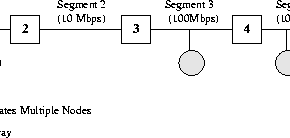
Figure:
The network
setup for multi-segment RETHER experiments. There are
four segments, two of them 100-Mbps and the other two 10-Mbps Ethernets.
 |
Next: Implementation and Performance
Up: Multi-Segment RETHER
Previous: Fault Tolerance
Tzi-cker Chiueh
1999-03-18