FlexFS: A Flexible Flash File System for MLC NAND Flash Memory
|
Abstract:The multi-level cell (MLC) NAND flash memory technology enables multiple bits of information to be stored on a single cell, thus making it possible to increase the density of the memory without increasing the die size. For most MLC flash memories, each cell can be programmed as a single-level cell or a multi-level cell during runtime. Therefore, it has a potential to achieve both the high performance of SLC flash memory and the high capacity of MLC flash memory.
In this paper, we present a flexible flash file system, called FlexFS, which takes advantage of the dynamic reconfiguration facility of MLC flash memory. FlexFS divides the flash memory medium into SLC and MLC regions, and dynamically changes the size of each region to meet the changing requirements of applications. We exploit patterns of storage usage to minimize the overhead of reorganizing two different regions. We also propose a novel wear management scheme which mitigates the effect of the extra writes required by FlexFS on the lifetime of flash memory. Our implementation of FlexFS in the Linux 2.6 kernel shows that it can achieve a performance comparable to SLC flash memory while keeping the capacity of MLC flash memory for both simulated and real mobile workloads.
As flash memory technologies quickly improve, NAND flash memory is becoming an attractive storage solution for various IT applications from mobile consumer electronics to high-end server systems. This rapid growth is largely driven by the desirable characteristics of NAND flash memory, which include high performance and low-power consumption.
There are two types of NAND flash memory in the market: a single-level cell (SLC) and a multi-level cell (MLC) flash memory. They are distinctive in terms of capacity, performance, and endurance. The capacity of MLC flash memory is larger than that of SLC flash memory. By storing two (or more) bits on a single memory cell, MLC flash memory achieves significant density increases while lowering the cost per bit over SLC flash memory which can only store a single bit on a cell. However, SLC flash memory has a higher performance and a longer cell endurance over MLC flash memory. Especially, the write performance of SLC flash memory is much higher than that of MLC flash memory.
As the demand for the high capacity storage system is rapidly increasing, MLC flash memory is being widely adopted in many mobile embedded devices, such as smart phones, digital cameras, and PDAs. However, because of a poor performance characteristic of MLC flash memory, it is becoming harder to satisfy users’ requirements for the high performance storage system while providing increased storage capacity.
To overcome this poor performance, in this paper, we propose exploiting the flexible programming feature of MLC flash memory [1]. Flexible programming is a writing method which enables each cell to be programmed as a single-level cell (SLC programming) or a multi-level cell (MLC programming). If SLC programming is used to write data into a particular cell, the effective properties of that cell become similar to those of an SLC flash memory cell. Conversely, MLC programming allows us to make use of the high capacity associated with MLC flash memory.
The most attractive aspect of flexible programming is that it allows fine-grained storage optimizations, in terms of both performance and capacity, to meet the requirements of applications. For instance, if the current capacity of flash memory is insufficient for some application, MLC flash memory can change its organization and increase the number of multi-level cells to meet the space requirement. However, to exploit flexible cell programming effectively, several issues need to be considered.
First, heterogeneous memory cells should be managed in a way that is transparent to the application layer, because flexible programming allows two different types of a cell to exist in the same flash chip simultaneously.
Second, dynamic cell reconfigurations between the SLC and MLC must be handled properly. For example, if too many flash cells are used as single-level cells, the capacity of flash memory might be critically impaired, even though the overall I/O performance is improved. Therefore, it is important to determine the number of SLC cells and MLC cells so that both the performance and capacity would be optimally supported.
Third, the cost of dynamic cell reconfigurations should be kept as low as possible. Changing the type of a cell requires expensive erase operations. Since an erase operation resets cells to their initial bit value (e.g., 1), the data stored in the cells must first be moved to elsewhere. The performance overhead of this data migration impairs the overall I/O performance.
Finally, write and erase operations required to change the type of a cell reduce the endurance of each cell, resulting in the decrease of the lifetime of flash memory. This problem also needs to be addressed properly.
In this paper, we propose a flexible flash file system, called FlexFS, for MLC flash memory that addresses the above requirements effectively. FlexFS provides applications with a homogeneous view of storage, while internally managing two heterogeneous memory regions, an SLC region and an MLC region. FlexFS guarantees the maximum capacity of MLC flash memory to users while it tries to write as much data as possible to the SLC region so as to achieve the highest I/O performance. FlexFS uses a data migration policy to compensate for the reduced capacity caused by overuse of the SLC region. In order to prolong the lifespan of flash memory, a new wear management scheme is also proposed.
In order to evaluate the effectiveness of FlexFS, we implemented FlexFS in the Linux 2.6.15 kernel on a development board. Evaluations were performed using synthetic and real workloads. Experimental results show that FlexFS achieves 90% of the read and 96% of the write performance of SLC flash memory, respectively, while offering the capacity of MLC flash memory.
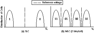
Figure 1: Threshold voltage distributions for SLC (1 bit/cell) and MLC (2 bits/cell)
The rest of this paper is organized as follows. In Section 2, we present a brief review of NAND flash memory and explain MLC flash memory in detail. In Section 3, we give an overview of FlexFS and introduce the problems that occur with a naive approach to exploiting flexible cell programming. In Section 4, we describe SLC and MLC management techniques. In Section 5, we present experimental results. Section 6 describes related work on heterogeneous storage systems. Finally, in Section 7, we conclude with a summary and future work.
NAND flash memory consists of multiple blocks, each of which is composed of several pages. In many NAND flash memories, the size of a page is between 512 B and 4 KB, and one block consists of between 4 and 128 pages. NAND flash memory does not support an overwrite operation because of its write-once nature. Therefore, before writing new data into a block, the previous data must be erased. Furthermore, the total number of erasures allowed for each block is typically limited to between 10,000 and 100,000 cycles.
Like SRAM and DRAM, flash memory stores bits in a memory cell, which consists of a transistor with a floating gate that can store electrons. The number of electrons stored on the floating gate determines the threshold voltage, Vt, and this threshold voltage represents the state of the cell. In case of a single-level cell (SLC) flash memory, each cell has two states, and therefore only a single bit can be stored in that cell. Figure 1(a) shows how the value of a bit is determined by the threshold voltage. If the threshold voltage is greater than a reference voltage, it is interpreted as a logical ‘1’; otherwise, it is regarded as a logical ‘0’. In general, the write operation moves the state of a cell from ‘1’ to ‘0’, while the erase operation changes ‘0’ to ‘1’.
If flash memory is composed of memory cells which have more than two states, it is called a multi-level cell (MLC) flash memory, and two or more bits of information can be stored on each cell, as shown in Figure 1(b). Even though the density of MLC flash memory is higher than that of SLC flash memory, it requires more precise charge placement and charge sensing (because of narrower voltage ranges for each cell state), which in turn reduces the performance and endurance of MLC flash memory in comparison to SLC flash memory.
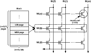
Figure 2: An organization of an MLC flash memory array (2 bits/cell)
In MLC flash memory, it is possible to use SLC programming, allowing a multi-level cell to be used as a single-level cell. To understand the implications of SLC programming, it is necessary to know the overall architecture of a flash memory array. Figure 2 illustrates the array of flash memory cells which forms a flash memory block. We assume that each cell is capable of holding two bits. For a description purpose, this figure does not show all the elements, such as source and drain select gates, which are required in a memory array. (For a more detailed description, see references [2, 3].)
As shown in Figure 2, the memory cells are arranged in an array of rows and columns. The cells in each row are connected to a word line (e.g., WL(0)), while the cells in each column are coupled to a bit line (e.g., BL(0)). These word and bit lines are used for read and write operations. During a write operation, the data to be written (‘1’ or ‘0’) is provided at the bit line while the word line is asserted. During a read operation, the word line is again asserted, and the threshold voltage of each cell can then be acquired from the bit line.
Figure 2 also shows the conceptual structure of a flash block corresponding to a flash memory array. The size of a page is determined by the number of bit lines in the memory array, while the number of pages in each flash block is twice the number of word lines, because two different pages share the memory cells that belong to the same word line. These two pages are respectively called the least significant bit (LSB) page and the most significant bit (MSB) page. As these names imply, each page only uses its own bit position of a bit pattern stored in a cell. (This is possible because each memory cell stores two bits, for example, one bit for the LSB page and the other for the MSB page.) Thus, if a block has 128 pages, there are 64 LSB and 64 MSB pages.
Because multiple pages are mapped to the same word line, read and write operations must distinguish the destination page of each operation. For example, if a cell is in an erased state (i.e., a logical ‘11’) and a logical ‘0’ is programmed to the MSB position of the cell, the cell will then have a bit pattern of ‘01’, which is interpreted as a logical ‘0’ for the MSB page. If the LSB position is then programmed as ‘0’, the bit pattern will change to ‘00’.
Since MLC flash memory stores multiple pages in the same word line, it is possible for it to act as SLC flash memory by using only the LSB pages (or MSB pages, depending on the manufacturer’s specification). Thus, SLC programming is achieved by only writing data to the LSB pages in a block. In this case, since only two states of a cell, ‘11’ and ‘10’, are used shown in Figure 1(b), the characteristics of a multi-level cell become very similar to those of a single-level cell. The logical offsets of the LSB and MSB pages in a block are determined by the flash memory specification, and therefore SLC programming can be managed at the file system level. Naturally, SLC programming reduces the capacity of a block by half, because only the LSB pages can be used.
Table 1 compares the performance of the three different types of cell programming method. The SLC column shows the performance data in a pure SLC flash memory; the MLCLSB column gives the performance data when only the LSB pages are used; and the MLCBOTH column gives the data when both the LSB and MSB pages are used. The access times for page reads and writes, and for block erase operations were measured using the Samsung’s KFXXGH6X4M flash memory [4] at the device driver interface level. As shown in Table 1, there are no significant performance differences between page read and block erase operations for the three programming methods. However, the write performance is significantly improved with MLCLSB, and approaches to that of SLC.
This improvement in the write performance under MLCLSB is the main motivation for FlexFS. Our primary goal is to improve the write performance of MLC flash memory using the MLCLSB method, while maintaining the capacity of MLC flash memory using the MLCBOTH method.
We will now describe the overall architecture of the proposed FlexFS system. FlexFS is based on JFFS2 file system [5], and hence the overall architecture is very similar to JFFS2 except for some features required to manage heterogeneous cells and to exploit flexible programming. Therefore, in this section, we focus on how FlexFS deals with different types of a cell. We also introduce a baseline approach to exploit flexible cell programming in order to illustrate the need for better policies, which will be introduced in detail on the following section.
Figure 3: The layout of flash blocks in FlexFS
In order to manage heterogeneous cells efficiently, FlexFS logically divides the flash memory medium into an SLC region, composed of SLC blocks, and an MLC region consisting of MLC blocks. If a block does not contain any data, it is called a free block. In FlexFS, a free block is neither an SLC block nor an MLC block; its type is only determined when data is written into it.
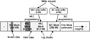
Figure 3 shows the layout of flash memory blocks in FlexFS. We assume that the number of pages in a block is 128, and the page size is 4 KB. (These values will be used throughout the rest of this paper.) When a write request arrives, FlexFS determines the type of region to which the data is to be written, and then stores the data temporarily in an appropriate write buffer. This temporary buffering is necessary because the unit of I/O operations is a single page in flash memory. Therefore, the write buffer stores the incoming data until there is at least the page size of data (i.e., 4 KB), which can be transferred to flash memory. In order to ensure the data reliability, if there is an explicit flush command from the operating system, all the pending data is immediately written to flash memory. In FlexFS, separate write buffers are used for the SLC and MLC regions.
FlexFS manages flash memory in a similar fashion to other log-structured file systems [5, 6, 7], except that two log blocks (one for the SLC and another for the MLC region) are reserved for writing. When data is evicted from the write buffer to flash memory, FlexFS writes them sequentially from the first page to the last page of the corresponding region’s log block. MLC programming is used to write data to the MLC block, and SLC programming is used to write to the SLC block. If existing data is updated, the old version of the data is first invalidated, while the new data is appended to the free space of a log block. The space used by this invalid data is later reclaimed by the garbage collector (Section 4.3).
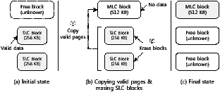
After all the free pages in the current log block have been exhausted, a new log block is allocated from the free blocks. However, if there is not enough free space to store the data, the data migrator triggers a data migration (Section 4.1.1) to create more free space. This expands the effective capacity of flash memory by moving the data from the SLC region to the MLC region. Figure 4 illustrates the steps in data migration. In this example, there are initially two SLC blocks and one free block, as shown in Figure 4(a). We assume that all the pages in the two SLC blocks contain valid data. During the data migration, the free block is converted into an MLC block, and the 128 pages in the two SLC blocks are copied to this MLC block. Then the two SLC blocks are erased, making them free blocks. This migration frees up one block, doubling the remaining capacity of flash memory, as shown in Figure 4(c).
Figure 4: Steps in data migration
When a read request arrives, FlexFS first checks whether the write buffers contain the requested data. If so, the data in the write buffer is transferred to the page cache. Otherwise, FlexFS searches an inode cache, which is kept in main memory, to find a physical address for the requested file data. The inode cache maintains the inode numbers and physical locations of data that belong to each inode. If the physical address of the required data is found, regardless of the type of block in which the data is stored, FlexFS can read the data from that address.
The major objective of FlexFS is to support both high performance and high capacity in MLC flash memory. A simplistic solution, which we call the baseline approach, is first to write as much data as possible into SLC blocks to maximize the I/O performance. When there are no more SLC blocks available, the baseline approach initiates a data migration so that more space becomes available for subsequent write requests, so as to maximize the capacity of flash memory. This simple approach has two serious drawbacks.
First, if the amount of data stored on flash memory approaches to half of its maximum capacity, almost all the free blocks are exhausted. This is because the capacity of the SLC block is half that of the MLC block. At this point, a data migration has to be triggered to free some blocks before writing the requested data. But, this reduces the overall I/O performance significantly. To address this problem, we introduce techniques to reduce the migration penalty, or to hide it from users.
Second, the baseline approach degrades the lifetime of MLC flash memory seriously. Each block of NAND flash memory has a finite number of erase cycles before it becomes unusable. The baseline approach tends to increase the number of erase operations because of the excessive data migration. In the worst case, the number of erasures could be three times more than in conventional flash file systems. We solve this problem by controlling the degree of the migration overhead, with the aim of meeting a given lifetime requirement.
To reduce or hide the overhead associated with data migrations, we introduce three techniques: background migration, dynamic allocation, and locality-aware data management. The background migration technique exploits the times when the system is idle to hide the data migration overhead. This technique is effective for many mobile embedded systems (e.g., mobile phones) which have long idle time. The dynamic allocation technique, on the other hand, is aimed at systems with less idle time. By redirecting part of the incoming data into the MLC region depending on the idleness of the system, it reduces the amount of data that is written into the SLC region, which in turn reduces the data migration overheads. The third technique, locality-aware data management, exploits the locality of I/O accesses to improve the efficiency of data migration. We will now look at these three techniques in more detail.
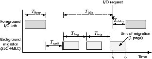
Figure 5: Overview of the background migration
Figure 5 shows the overall process of the background migration. In this figure, the X-axis shows the time and the Y-axis gives the type of job being performed by the file system. A foreground job represents I/O requests issued by applications or the operating system. Tbusy is a time interval during which the file system is too busy to process foreground jobs, and Tidle is an idle interval. During this idle time the background migrator can move data from the SLC region to the MLC region, thus freeing many blocks. These free blocks can then be used as SLC blocks to store data, and so we can avoid a compulsory data migration if there is sufficient idle time.
In designing the background migration technique, there are two important issues: First, it is important to minimize the delay in response time Tdelay inflicted on foreground tasks by the background migration. For example, in Figure 5, an I/O request arrives at t1, but it cannot proceed until t2 because of interference from the background migration. So Tdelay is t2 - t1. To reduce this delay, the data migrator monitors the I/O subsystem, and suspends the background migration process if there is an I/O request. Since the unit of a data migration is a single page, the maximum delay in response time will be less than the time required to move a page from SLC to MLC (about 1,403 us) theoretically. In addition, we also design the background migrator so that it does not utilize all available idle times. Instead, it periodically invokes a data migration at a predefined triggering interval Ttrig. If Ttrig is larger than the time required to move a single page, FlexFS reduces the probability that a foreground job will be issued while a data migration is running, thus further reducing Tdelay.
The second issue is when to initiate a background migration. Our approach is based on a threshold; if the duration of the idle period is longer than a specific threshold value Twait, then the background migrator is triggered. This kind of problem has been extensively studied in dynamic power management (DPM) of hard disk drives [8], which puts a disk into a low-power state after a certain idle time in order to save energy. However, the transition to a low-power state has to be made carefully because it introduces a large performance penalty. Fortunately, because Tdelay is quite short, more aggressive transitioning is possible in our background migration technique, allowing Twait to be set to a small value.
The background migration technique works well when a system has sufficient idle time. Otherwise, the migration overhead cannot be avoided. But it can be ameliorated by writing part of the incoming data into the MLC region, so as to reduce the amount of data to be moved by the background migrator. Although this approach results in a lower I/O performance than SLC flash memory, it can prevent significant performance degradation due to a compulsory data migration.
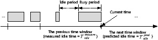
The dynamic allocator determines the amount of data that will be written into the SLC region. Intuitively, it is clear that this must depend on how much idle time there is in a given system. Since the amount of idle time changes dynamically with user activities, we need to predict it carefully. Figure 6 illustrates the basic idea of our idle time prediction approach, which is based on previous work [9]. In this figure, each time window represents the period during which Np pages are written into flash memory. The dynamic allocator stores measured idle times for several previous time windows, and uses them to predict the idle time, Tidlepred, for the next time window. The value of Tidlepred is a weighted average of the idle times for the latest 10 time windows; the three most recent windows are given a higher weight to take the recency of I/O pattern into account.
Figure 6: Our approach to idle time prediction
If we know the value of Tidlepred, we can use it to calculate an allocation ratio, denoted by α, which determines how many pages will be written to the SLC region in the next time window. The value of α can be expressed as follows:
| α = | ⎧ ⎪ ⎪ ⎨ ⎪ ⎪ ⎩ |
| (1) |
| where Tmig = Np · (Ttrig + TeraseSLC/SpSLC), (2) |
where TeraseSLC is the time required to erase an SLC flash block which contains SpSLC pages. As mentioned in Section 4.1.1, Ttrig is the time interval required for one page to migrate from the SLC region to the MLC region. Therefore, Tmig is the migration time, which includes the time taken to move all Np pages to the MLC region and the time for erasing all used SLC blocks. If Tidlepred ≥ Tmig, there is sufficient idle time for data migrations, and thus α = 1. Otherwise, the value of α should be reduced so that less data is written into the SLC region, as expressed by Eq. (1).
Once the value of α has been determined, the dynamic allocator tries to distribute the incoming data across the different flash regions depending on α. Therefore, the number of pages to be written into the SLC region, NpSLC, and the amount of data destined for the MLC region, NpMLC, can be expressed as follows:
| NpSLC = Np · α, NpMLC = Np · (1 − α). (3) |
Finally, after writing all Np pages, the dynamic allocator calculates a new value of α for the next Np pages.
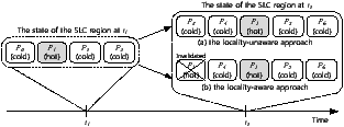
Figure 7: A comparison of the locality-unaware and locality-aware approaches
FlexFS is based on a log-structured file system, and therefore it uses the out-place update policy. Under this policy, hot data with a high update frequency generates more outdated versions of itself than cold data, which is updated infrequently. Our locality-aware data management technique exploits this characteristic to increase the efficiency of data migration.
Figure 7 compares the locality-aware and the locality-unaware approaches. We assume that, at time t1, three cold pages p0, p2, and p3, and one hot page p1, exist in the SLC region. Between t1 and t2, there are some idle periods, and new pages p1, p4, p5, and p6 are written into the SLC region. Note that p1 is rewritten because it contains hot data. In the case of the locality-unaware approach shown in Figure 7(a), we assume that pages p0, p1, and p2 are moved to the MLC region during idle time, but p3 cannot be moved because there is not enough idle time. Therefore, at time t2, there are five pages in the SLC region. If the value of Np is 4, the value of α should decrease so that data will not accumulate in the SLC region. However, if we consider the locality of the data, we can move p3 instead of p1 during idle periods, as shown in Figure 7(b). Since p1 has a high locality, it is highly likely to be invalidated by t2. Therefore, an unnecessary page migration for p1 can be avoided, and only four pages remain in the SLC region. In this case, we need not to reduce the value of α, and more data will be written into the SLC region.
Using this observation, Eq. (2) can be rewritten as follows:
| Tmig = (Np − Nphot) · (Ttrig + TeraseSLC/SpSLC), (4) |
where Nphot is the number of page writes for hot pages stored in the SLC region. For instance, in the above example, Nphot is 1. Because we only need to move Np - Nphot pages into the MLC region, the value of Tmig can be reduced, allowing an increase in α for the same amount of idle time.
To exploit the locality of I/O references, there are two questions to answer. The first is to determine the locality of a given data. To know the hotness of data, FlexFS uses a 2Q-based locality detection technique [10], which is widely used in the Linux operating system. This technique maintains a hot and a cold queue, each containing a number of nodes. Each node contains the inode number of a file. Nodes corresponding to frequently accessed files are stored on the hot queue, and the cold queue contains nodes for infrequently accessed files. The locality of a given file can easily be determined from queue in which the corresponding node is located.
Second, the data migrator and the dynamic allocator should be modified so that they take the locality of data into account. The data migrator tries to select an SLC block containing cold data as a victim, and an SLC block containing hot data is not selected as a victim unless very few free blocks remain. Since a single block can contain multiple files which have different hotness, FlexFS calculates the average hotness of each block as the criterion, and chooses a block whose hotness is lower than the middle. It seems better to choose a block containing only cold pages as a victim block; if there are only a few bytes of hot data in a victim, this results in useless data migrations for hot data. However, this approach incurs the delay in reclaiming free blocks, because even if the small amount of hot data is stored on a block, the block will not be chosen as a victim.
The dynamic allocator tries to write as much hot data to the SLC region as possible in order to increase the value of Nphot. The dynamic allocator also calculates a new value of α after Np pages have been written and, for this purpose, the value of Nphot for the next time window need to be known. Similar to the approach used in our idle time prediction, we count how many hot pages were written into the SLC region during the previous 10 time windows, and use their average hotness value as Nphot for the next time window. The value of Nphot for each window can be easily measured using an update variable, which is incremented whenever a hot page is sent to the SLC region.
To enhance the endurance of flash memory, many flash file systems adopt a special software technique called wear-leveling. In most existing wear-leveling techniques, the primary aim is to distribute erase cycles evenly across the flash medium [11, 12]. FlexFS uses this approach, but also needs to support more specialized wear management to cope with frequent data migrations.
The use of FlexFS means that each block undergoes more erase cycles because a lot of data is temporarily written to the SLC region, waiting to move to the MLC region during idle time. To improve the endurance and prolong the lifetime, it would be better to write data to the MLC region directly, but this reduces the overall performance. Therefore, there is another important trade-off between the lifetime and performance.
To efficiently deal with this trade-off, we propose a novel wear management technique which controls the amount of data to be written into the SLC region depending on a given storage lifetime.
We start by introducing a new endurance metric which is designed to express the trade-off between lifetime and performance. In general, the maximum lifetime, Lmax, of flash memory depends on the capacity and the amount of data written to them, and is expressed as follows:
| Lmax = |
| , (5) |
where Ctotal is the size of flash memory, and Ecycles is the number of erase cycles allowed for each block. The writing rate WR indicates the amount of data written in unit time (e.g., per day). This formulation of Lmax is used by many flash memory manufacturers [13] because it clearly shows the lifetime of a given flash application under various environments.
Unfortunately, Lmax is not appropriate to handle the trade-off between lifetime and performance because it expresses the expected lifetime, and not the constraints to be met in order to improve the endurance of flash memory. Instead, we use an explicit minimum lifespan, Lmin, which represents the minimum guaranteed lifetime that would be ensured by a file system. Since FlexFS can control the writing rate WR by adjusting the amount of data written into the SLC region, this new endurance metric can be expressed as follows:
| (6) |
where δ is called the wear index. In FlexFS δ is proportional to WR, and therefore δ can be used to control the value of WR. If δ is high, FlexFS writes a lot of data to the SLC region; and this increases WR due to data migrations; but if δ is low, the writing rate is reduced. Our wear management algorithm controls δ so that the lifetime specified by Lmin is to be satisfied.
The proposed wear management algorithm divides the given lifetime Lmin into n time windows (w0, w1, ... , wn−2, wn−1), and the duration of each window is given as Ts. The writing rate WR(wi) for each time window wi can also be expressed as WB(wi) / Ts, where WB(wi) is the amount of data and represents the writing budget assigned to the time window wi.
Since Ts is fixed, the assignment of a writing budget to each window significantly impacts the overall performance as well as the rate at which flash memory wears out. For example, if too large a writing budget is assigned to each window, it markedly increases the number of erase cycles for each block; on the other hand, if too small a writing budget is allocated, it lowers the overall performance. Therefore, we determine a writing budget for the window wi as follows:
| WB(ti) = |
| , (7) |
where ti is the time at the start of window wi, and W(ti) indicates the amount of a writing budget that has actually been used by ti. The remaining writing budget is (Ctotal · Ecycles) − W(ti), and the number of remaining windows is (n − (ti / Ts)). Therefore, the remaining writing budget is shared equally between the remaining windows. The writing budget is calculated at the beginning of every time window, so as to take changes in the workload pattern into consideration.
Once the writing budget has been assigned to a time window, the wear manager adjusts the wear index, δ, so that the amount of a writing budget actually used approximates the given writing budget. The wear index is used by a dynamic allocator, similar to Eq. (3), to distribute the incoming data across the two regions.
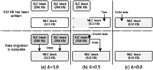
Figure 8: How the number of blocks used depends on δ
Figure 8 shows how the number of blocks used depends on the value of δ. The size of the SLC and MLC blocks is 256 KB and 512 KB, respectively. Suppose that 512 KB data is written, and the data migrator moves this data from the SLC region to the MLC region. If δ is 1.0, as shown in Figure 8(a), 512 KB is written to two SLC blocks, and then the data migrator requires one MLC block to store the data from two SLC blocks. In this case, the total amount of a writing budget used is 1.5 MB because three blocks have been used for writing. If δ is 0.5, as shown in Figure 8(b), 1 MB of a writing budget is used, requiring one SLC block and one MLC block. Figure 8(c) shows the case when δ is 0.0. Only 512 KB is used because there is no data to be moved.
This simple example suggests that we can generalize the relationship between the wear index, the amount of incoming data, and the amount of a writing budget actually used, as follows:
| (8) |
where IW(wi) is the amount of data that arrives during the window wi, and OW(wi) is the amount of a writing budget to be used depending on δ. In the example of Figure 8(b), IW(ti) is 512 KB and δ is 0.5, and thus OW(ti) is 1 MB. IW(wi) · (2 · δ) is the amount of a writing budget used by the SLC region and IW(wi) is the amount of data to be written to the MLC region.
The wear index should be chosen so that OW(wi) = WB(ti), and can therefore be calculated as follows:
| (9) |
The value of δ is calculated at the beginning of wi when the exact value of IW(wi) is unknown. IW(wi) is therefore estimated to be the average value of the previous three time windows. If WB(ti) < IW(wi), then δ is 0, and therefore all the data will be written to the MLC region. If IW(wi) is always larger than WB(ti), it may be hard to guarantee Lmin. However, by writing all the data to the MLC region, FlexFS can achieve a lifetime close to that of a pure MLC flash memory.
A newly determined value of δ is only used by the dynamic allocator if δ < α. Therefore, the wear management algorithm is only invoked when it seems that the specified lifetime will not be achieved.
The data migrator can make free blocks by moving data from the SLC region to the MLC region, but it cannot reclaim the space used by invalid pages in the MLC region. The garbage collector, in FlexFS, reclaims these invalid pages by selecting a victim block in the MLC region, and then by copying valid pages in the victim into a different MLC block. The garbage collector selects a block with many invalid pages as a victim to reduce the requirement for additional I/O operations, and also utilizes idle times to hide this overhead from users. Note that, it is never necessary to choose a victim in the SLC region. If cold data is stored in SLC blocks, it will be moved to the MLC region by the data migrator; but hot data need not to be moved because it will soon be invalidated.
Figure 9: A snapshot of the flash development board used for experiments
In order to evaluate the efficiency of the proposed techniques on a real platform, we implemented FlexFS on Linux 2.6.25.14 kernel. Our hardware system was the custom flash development board shown in Figure 9, which is based on TI’s OMAP2420 processor (running at 400 MHz) with a 64 MB SDRAM. The experiments were performed on Samsung’s KFXXGH6X4M-series 1-GB flash memory [4], which is connected to one of the NAND sockets shown in Figure 9. The size of each page was 4 KB and there were 128 pages in a block.
To evaluate the FlexFS file system objectively, we used two types of workload. In Section 5.1, we present experimental results from synthetic workloads. In Section 5.2, we evaluate FlexFS using actual I/O traces collected from executions of real mobile applications.
Table 2 summarizes the configurations of the four schemes that we used for evaluating the throughput of FlexFS. In the baseline scheme, all the data is first written into SLC blocks, and then compulsorily moved to MLC blocks only when fewer than five free blocks remain. Three other schemes, BM, DA, and LA, use techniques to reduce the overhead of data migrations. For example, the BM scheme uses only the background migration technique, while the LA scheme uses all three proposed techniques. In all the experiments, Twait was set to 1 second, Np was 1024 pages, and Ttrig was 15 ms. To focus on the performance implications of each scheme, the wear management scheme was disabled.
All the schemes were evaluated on three synthetic benchmark programs: Idle, Busy, and Locality. They were designed to characterize several important properties, such as the idleness of the system and the locality of I/O references, which give significant effects on the performance of FlexFS. The Idle benchmark mimics the I/O access patterns that occur when sufficient idle time is available in a system. For this purpose, the Idle benchmark writes about 4 MB of data (including metadata) to flash memory every 25 seconds. The Busy benchmark generates 4 MB of data to flash memory every 10 seconds, which only allows the I/O subsystem small idle times. The Locality benchmark is similar to Busy, except that about 25% of the data is likely to be rewritten to the same locations, so as to simulate the locality of I/O references that occurs in many applications. All the benchmarks issued write requests until about 95% of the total MLC capacity has been used. To speed up the evaluation, we limited the capacity of flash memory to 64 MB using the MTD partition manager [14].
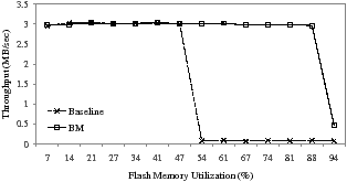
Figure 10: Performance comparison of Baseline and BM with the Idle benchmark
Figure 10 compares the throughput of Baseline and BM with the Idle benchmark. The throughput of Baseline is significantly reduced close to 100 KB/s when the utilization approaches 50%, because before writing the incoming data, the data migrator should make enough free space in the SLC region, incurring a noticeable performance degradation. However, BM achieves the same performance as SLC flash memory until the utilization exceeds 94%. Since the Idle benchmark allows FlexFS a lot of idle time (about 93.6% of the total execution time), it should be possible to reclaim a sufficient number of free blocks before new write requests arrive and require them. When the utilization reaches 94%, the performance of BM is significantly reduced because almost all of the available blocks is occupied by valid data, and fewer than 5 free blocks remain available.
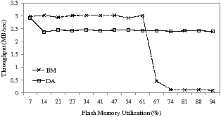
Figure 11: Performance comparison of BM and DA with the Busy benchmark
Figure 11 compares the performance of BM and DA while running the Busy benchmark. In this evaluation, BM shows a better throughput than DA when the utilization is less than 67%. However, its performance quickly declines because the idle time is insufficient to allow BM to generate enough free blocks to write to the SLC region. DA does exhibit a stable write performance, regardless of the utilization of flash memory. At the beginning of the run, the value of α is initially set to 1.0 so that all the incoming data is written to the SLC region. However, since insufficient idle time is available, the dynamic allocator adjusts the value of α to 0.5. DA then writes some of the arriving data directly to the MLC region, avoiding a significant drop in performance.
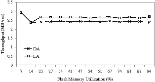
Figure 12 shows the performance benefit of the locality-aware approach using the Locality benchmark. Note that Locality has the same amount of idle time compared as the Busy benchmark. LA achieves 7.9% more write performance than DA by exploiting the locality of I/O references. The overall write throughput of LA is 2.66 MB/s while DA gives 2.45 MB/s. The LA scheme also starts with an α value of 1.0, but that is reduced to 0.5 because the idle time is insufficient. However, after detecting a high degree of locality from I/O references, α is partially increased to 0.7 by preventing useless data migrations of hot data, and more data can then be written into the SLC region.
Figure 12: Performance comparison of DA and LA with the Locality benchmark
Although the background migration contributes to improving the write throughput of FlexFS, it could incur a substantial increase in response time because I/O requests can be issued while the background migrator is running. In this subsection, to investigate the impact of the background migration on the response time, we performed evaluations with a following scenario.
We first wrote 30 MB of bulk data in order to trigger the background migrator. FlexFS was modified for all the incoming data to be written into the SLC region, regardless of the amount of idle time. After writing this data, we made 10 page write requests. The idle time between two consecutive write requests was generated using a pseudo-random number generator, but this was adjusted at least larger than Twait so that all write requests was randomly issued after the background migrator has been initiated. To collect accurate and reliable results, we performed this scenario more than 30 times.
We performed our evaluation for the following four configurations. In order to know the effect of the idle time utilization, we measured the response time while varying the idle time utilization. The configurations, U100, U50, and U10 represent when FlexFS utilizes 100%, 50%, and 10% of the total idle time, respectively. This idle time utilization can be easily controlled by the value of Ttrig. For example, the time required to move a single page from SLC to MLC is about 1.5 ms, and so the utilization of 10% can be made using Ttrig of 15 ms. To clearly show the performance penalty from the background migration, we evaluated the response time when the background migration is disabled, which is denoted as OPT. The migration suspension mentioned in Section 4.1.1 was enabled for all the configurations.
Figure 13: A comparison of response time delays on different system configurations
Figure 13 shows the cumulative distribution function of the response time for the four configurations. As expected, OPT shows the best response time among all the configurations. However, about 10% of the total I/O requests requires more than 2,000 us. This response time delay is caused by the writing of the metadata information. Although we wrote 4 KB of data into flash memory, the amount of data actually written was slightly larger than 4 KB because of the metadata overhead. Consequently, this results in additional page writes, incurring the delay in response time.
U10 exhibits a longer response time than OPT for about 10% of the total I/O requests, but it shows a fairly good response time. On the other hand, the performance of U50 and U100 is significantly deteriorated because they utilize a lot of idle time for data migrations, increasing the probability of I/O requests being issued while the background migrator is working. Especially, when two tasks (the foreground task and the background migration task) compete for a single CPU resource, the performance penalty caused by the resource contention is more significant than we expect.
We evaluated our wear management scheme using a workload scenario in which the write patterns change over a relatively long time. We set the size of flash memory, Ctotal, to 120 MB, and the number of erase cycles allowed for each block, Ecycles, was 10, allowing a maximum of 1.2 GB to be written to flash memory. We set the minimum lifetime, Lmin, to 4,000 seconds, and our wear management scheme was invoked every 400 seconds. So, there are 10 time windows, w0, ..., w9, and the duration of each, Ts, is 400 seconds. To focus our evaluation on the effect of the wear management scheme on performance, the system was given enough idle time to write all the data to the SLC region if the lifetime of flash memory is not considered.
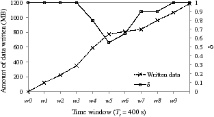
Figure 14: The changes in the size of written data and the δ value
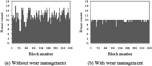
Figure 15: Distributions of block erase cycles
Table 3 shows the amount of data (MB) written to flash memory for each window, wi, and Figure 14 shows how the proposed wear management scheme adapts to changing write sizes while satisfying the minimum lifetime. Initially, FlexFS allocates a writing budget of 120 MB (= 1.2 GB / 10) to each time window. This budget is large enough to allow all the incoming data to be written to the SLC region if less than or equal to 40 MB of data arrives during each window. Therefore, during the first three windows, the value of δ is set to 1.0. During w3 and w4, however, about 160 MB of data arrives, and FlexFS reduces δ to cut the migration cost. Because only 40 MB of data arrives during w5 and w6, FlexFS can increase δ to give a larger writing budget to the remaining windows. We measured the amount of data written to flash memory, including extra overheads caused by migrations from the SLC region to the MLC region. FlexFS writes about 1.2 GB of data to flash memory, and thus achieving the specified minimum life span of 4,000 seconds.
We also counted the number of erase operations performed on each block while running FlexFS with and without the wear management scheme using the same workload scenario. A wear-leveling policy was disabled when the wear management scheme was not used. Figure 15 shows distributions of block erase cycles, and Table 4 summarizes the results relevant to a wear-leveling. These results clearly indicate that with the wear management scheme FlexFS gives a good wear characteristic; the maximum erase cycle of each block is effectively limited to less than or equal to 10, and the block erase operations are evenly distributed across the flash memory medium.
In addition to the synthetic workloads discussed in Section 5.1, which were designed to evaluate one aspect of FlexFS at a time, we evaluated FlexFS using I/O traces collected from a real-world mobile platform to assess the performance of FlexFS with mobile applications.
To collect and replay I/O traces from real applications, we developed a custom mobile workload generation environment based on the Qtopia Phone Edition [15], which includes representative mobile applications such as PIMS, SMS, and media players. This environment includes three tools: a usage pattern generator, an I/O tracer, and a replayer. The usage pattern generator automatically executes mobile applications as if the user is actually interacting with applications during runtime. The I/O tracer captures I/O system calls (e.g., fopen, fread, and fwrite) while running the usage pattern generator on the Qtopia platform, and then stores collected traces in a log file. The replayer uses this log file to replay the I/O requests in our development board. Note that this log file allows us to repeat the same usage patterns for different system configurations.
For the evaluation, we executed the several mobile applications shown in Table 5 on our workload generation environment for 30 minutes. We followed a representative usage profile of mobile users reported in [16] except that more multimedia data was written in order to simulate data downloading scenario. The trace includes 43,000 read and write requests. About 5.7 MB was read from flash memory and about 39 MB was written.
In order to find out whether FlexFS can achieve SLC-like performance, we evaluated the performance of two FlexFS configurations, FlexFSMLC and FlexFSSLC. FlexFSMLC is the proposed FlexFS configuration using both SLC and MLC programming, while FlexFSSLC mimics SLC flash memory by using only SLC programming. To know the performance benefits of FlexFSMLC, we evaluated JFFS2 file system on the same hardware. In this subsection, we will focus on the performance aspect only, since the capacity benefit of FlexFSMLC is clear.
For FlexFSMLC, Ttrig was set to 15 ms, Np to 1024 pages, and Twait to 1 second. We assumed a total capacity of 512 MB, a maximum of 10,000 erase cycles for a block, and a minimum lifetime of 3 years. The wear management policy was invoked every 10 minutes.
Table 6 compares the response time and the throughput of FlexFSMLC, FlexFSSLC, and JFFS2. The response time was an average over all the I/O requests in the trace file, but the throughput was measured when writing a large amount of data, such as MP3 files. Compared to JFFS2, FlexFSMLC achieves 28% smaller I/O response time and 28% higher I/O throughput. However, the performance difference between FlexFSMLC and JFFS2 is noticeably reduced compared to the difference shown in Table 1 because of computational overheads introduced by each file system. JFFS2 as well as FlexFSMLC requires a lot of processing time for managing internal data structures, such as block lists, a metadata, and an error detecting code, which results in the reduction of the performance gap between two file systems.
The performance of FlexFSMLC is very close to that of FlexFSSLC. The response times of FlexFSMLC are 10% and 3.2% slower for reads and writes, compared with FlexFSSLC. The I/O throughput of FlexFSMLC is 3.4% lower than that of FlexFSSLC. This high I/O performance of FlexFSMLC can be attributed to the sufficiency of idle time in the trace. Therefore, FlexFSMLC can write most incoming data into the SLC region, improving the overall I/O performance.
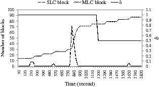
The graph in Figure 16 shows in more detail how FlexFSMLC achieves I/O efficiency. We counted the number of each type of block every 30 seconds. In the graph, the regions around 840 seconds clearly demonstrate the effectiveness of the proposed techniques. Starting from 750 seconds, many MP3 files of about 18 MB are intensively written into flash memory. FlexFSMLC can write all this data into the SLC region because the idle time predictor in the dynamic allocator predicts there will be enough idle time, which allows aggressive writes to the SLC region.
Figure 16: The changes in the number of SLC and MLC blocks with a mobile workload in FlexFSMLC
From our observations on the representative mobile workloads, there are two distinctive characteristics in I/O access patterns. First, many mobile embedded systems such as mobile phones and smart phones are likely to have sufficient idle time; the average idle time accounts for about 89% of the total execution time. Second, most data is intensively written to flash memory within a short time interval. As the experimental results show, FlexFS is effectively designed for dealing with such characteristics, and thus can achieve the I/O performance close to SLC flash memory.
The small performance penalty of FlexFSMLC results from ensuring the given minimum lifetime. As shown in Figure 16, at around 1,200 seconds the wear management policy reduces the value of δ to 0.5, which degrades the write performance of FlexFSMLC. However, this decision was necessary because a large number of writes to the SLC region for storing several MP3 files reduced the number of erase cycles significantly. To meet the required minimum lifetime, FlexFS wrote 50% of the data to the MLC region directly. This result indicates that the poor wear characteristic of MLC flash memory could be a hurdle for FlexFS to achieve its performance benefit.
However, it must be noted that 512 MB of flash capacity used in our evaluation is very small compared to commercial flash applications. Actually, many flash devices already employ several GB of flash memory and its capacity doubles every two or three years. For example, if a flash device has 16 GB MLC flash memory and the minimum lifetime is set to 3 years, the writing budget per day is about 146 GB. Therefore, it may safely be assumed that the endurance problem would be mitigated without a significant performance degradation.
Many file systems for NAND flash memory have been studied in recent years. JFFS2 [5] and YAFFS [7] are representative, and are both the log-structured file systems [6], which write data sequentially to NAND flash memory. JFFS2 was originally developed for NOR flash memory, and later extended to NAND devices. JFFS2 stores metadata and regular data together. YAFFS is similar to JFFS2 except that metadata is stored in a spare area of each page to promote fast mounting of the file system. They are both designed for the homogeneous flash memory media, and do not support the heterogeneous flash memory devices discussed in this paper.
Recently, there have been several efforts to combine both SLC and MLC flash memory. Chang et al. suggest a solid-state disk which is composed of a single SLC chip and many MLC chips [17], while Park et al. present a flash translation layer for mixed SLC-MLC storage systems [18]. The basic idea of these two approaches is to store frequently updated data in the small SLC flash memory while using the large MLC flash memory for storing bulk data. This brings the overall response time close to that of SLC flash memory while keeping the cost per bit as low as MLC flash memory. However, these approaches cannot break down when a large amount of data has to be written quickly, because they only use the small SLC flash memory so as to achieve their cost benefit. In this situation, the overall I/O throughput will be limited to the throughput of MLC flash memory. But FlexFS can handle this case efficiently by flexibly increasing the size of the SLC region, and therefore combines the high performance of SLC flash memory with the high capacity of MLC flash memory.
The hybrid hard disk [19, 20] is another heterogeneous storage system which uses flash memory as a non-volatile cache for a hard disk. In a hybrid hard disk, flash memory is used to increase the system responsiveness, and to extend battery lifetime. However, this approach is different from our study in which it does not give any considerations on optimizing the storage system by dynamically changing its organization.
FlexFS is a file system that takes advantage of flexible programming of MLC NAND flash memory. FlexFS is designed to maximize I/O performance while making the maximum capacity of MLC flash memory available. The novel feature of FlexFS is migration overhead reduction techniques which hide the incurred migration overhead from users. FlexFS also includes a novel wear management technique which mitigates the effect of the data migration on the lifetime of flash memory. Experimental results show that FlexFS achieves 90% and 96% of the read and write performance of SLC flash memory with real-world mobile workloads.
There are a few areas where FlexFS can be further improved. First, even though the background migration is effective in hiding the migration overhead, it is less efficient from the energy consumption perspective because it reduces the probability that the system enters a low-power state. In order to better handle both the performance and energy consumption simultaneously, we are developing a dynamic allocation policy that takes into account an energy budget of a system. Second, for FlexFS to be useful on a wide range of systems, the poor wear characteristic of MLC flash memory should be addressed properly. To handle this problem, we are also investigating a wear management policy for a storage architecture in which SLC flash memory is used as a write buffer for MLC flash memory.
This work was supported by the Korea Science and Engineering Foundation (KOSEF) grant funded by the Korea government (No. R0A-2007-000-20116-0) and the Brain Korea 21 Project in 2009. This work was also supported by World Class University (WCU) program through KOSEF funded by the Ministry of Education, Science and Technology (No. R33-2008-000-10095-0). Samsung Electronics partially supported our FlexFS research and the ICT at Seoul National University provided research facilities for this study.
This document was translated from LATEX by HEVEA.