
Hitesh Ballani
Cornell University
Paul Francis
Cornell University
Tuan Cao
Cornell University
Jia Wang
AT&T Labs - Research
We evaluate the application of ViAggre to a few tier-1 and tier-2 ISPs and show that it can reduce the routing table on routers by an order of magnitude while imposing almost no traffic stretch and negligible load increase across the routers. We also deploy Virtual Aggregation on a testbed comprising of Cisco routers and benchmark this deployment. Finally, to understand and address concerns regarding the configuration overhead that our proposal entails, we implement a configuration tool that automates ViAggre configuration. While it remains to be seen whether most, if not all, of the management concerns can be eliminated through such automated tools, we believe that the simplicity of the proposal and its possible short-term impact on routing scalability suggest that it is an alternative worth considering.
The increase in the size of the DFZ routing table
has several harmful implications for
inter-domain routing.![[*]](footnote.png) [31]
discusses these in detail.
At a technical level, increasing routing table size may drive high-end router
design into various engineering limits. For instance, while
memory and processing speeds might just scale with a growing
routing system, power and heat dissipation capabilities may
not [30].
On the business side, the performance requirements for forwarding while
being able to access a large routing table imply that the cost of forwarding packets increases and hence,
networks become less cost-effective [27]. Further,
it makes provisioning of networks harder since
it is difficult to
estimate the usable lifetime of routers, not to mention the cost of
the actual upgrades.
As a matter of fact, instead of
upgrading their routers, a few ISPs have resorted to filtering out
some small prefixes (mostly /24s) which implies that parts of the
Internet may not have reachability to each other [19].
This suggests that ISPs are willing to
undergo some pain to avoid the cost of router upgrades.
[31]
discusses these in detail.
At a technical level, increasing routing table size may drive high-end router
design into various engineering limits. For instance, while
memory and processing speeds might just scale with a growing
routing system, power and heat dissipation capabilities may
not [30].
On the business side, the performance requirements for forwarding while
being able to access a large routing table imply that the cost of forwarding packets increases and hence,
networks become less cost-effective [27]. Further,
it makes provisioning of networks harder since
it is difficult to
estimate the usable lifetime of routers, not to mention the cost of
the actual upgrades.
As a matter of fact, instead of
upgrading their routers, a few ISPs have resorted to filtering out
some small prefixes (mostly /24s) which implies that parts of the
Internet may not have reachability to each other [19].
This suggests that ISPs are willing to
undergo some pain to avoid the cost of router upgrades.
Such concerns regarding FIB size growth, along with problems arising from a large RIB and the concomitant convergence issues, were part of the reasons that led a recent Internet Architecture Board workshop to conclude that scaling the routing system is one of the most critical challenges of near-term Internet design [30]. The severity of these problems has also prompted a slew of routing proposals [7,11,32,29,14,8,18,40]. All these proposals require changes in the routing and addressing architecture of the Internet. This, we believe, is the nature of the beast since some of the fundamental Internet design choices limit routing scalability; the overloading of IP addresses with ``who'' and ``where'' semantics represents a good example [30]. However, the very fact that they require architectural change has contributed to the non-deployment of these proposals.
This paper takes the position that a major architectural change is unlikely and it may be more pragmatic to approach the problem through a series of incremental, individually cost-effective upgrades. Guided by this and the aforementioned implications of a rapidly growing DFZ FIB, this paper proposes Virtual Aggregation or ViAggre, a scalability technique that focuses primarily on shrinking the FIB size on routers. ViAggrea ``configuration-only'' solution that applies to legacy routers. Further, ViAggrebe adopted independently and autonomously by any ISP and hence the bar for its deployment is much lower. The key idea behind ViAggrevery simple: an ISP adopting ViAggre divides the responsibility for maintaining the global routing table amongst its routers such that individual routers only maintain a part of the routing table. Thus, this paper makes the following contributions:
Overall, the incremental version of ViAggrethis paper presents can be seen as little more than a simple and structured hack that assimilates ideas from existing work including, but not limited to, VPN tunnels and CRIO [40]. We believe that its very simplicity makes ViAggreattractive short-term solution that provides ISPs with an alternative to upgrading routers in order to cope with routing table growth till more fundamental, long-term architectural changes can be agreed upon and deployed in the Internet. However, the basic ViAggrecan also be applied in a clean-slate fashion to address routing concerns beyond FIB growth. While we defer the design and the implications of such a non-incremental ViAggrefor future work, the notion that the same concept has potential both as an immediate alleviative and as the basis for a next-generation routing architecture seems interesting and worth exploring.
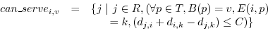
The virtual prefixesnot topologically valid aggregates, i.e. there is not a single point in the Internet topology that can hierarchically aggregate the encompassed prefixes. ViAggrethe virtual prefixes aggregatable by organizing virtual networks, one for each virtual prefix. In other words, a virtual topology is configured that causes the virtual prefixes to be aggregatable, thus allowing for routing hierarchy that shrinks the routing table. To create such a virtual network, some of the ISP's routers are assigned to be within the virtual network. These routers maintain routes for all prefixes in the virtual prefixto the virtual networkhence, are said to be aggregation points for the virtual prefix. A router can be an aggregation pointmultiple virtual prefixesis required to only maintain routes for prefixes in the virtual prefixesis aggregating.
Given this, a packet entering the ISP's network is routed to a
close-by aggregation pointthe virtual prefixthe actual destination
prefix. This aggregation pointa route for the
destination prefix and forwards the packet out of the ISP's
network in a tunnel. In figure 1 (figure
details explained later), router C is an aggregation pointthe virtual prefixthe destination prefix and
B
![]() C
C
![]() D is one such path through the ISP's network.
D is one such path through the ISP's network.
These goals, in turn, limit what can be achieved through the ViAggre designs presented here. Routers today have a Routing Information Base (RIB) generated by the routing protocols and a Forwarding Information Base (FIB) that is used for forwarding the packets. Consequently, the FIB is optimized for looking up destination addresses and is maintained on fast(er) memory, generally on the line cards themselves [31]. All things being equal, it would be nice to shrink both the RIB and the FIB for all ISP devices, as well as make other improvements such as shorter convergence time.
While the basic ViAggrecan be used to achieve these benefits (section VI), we have not been able to reconcile them with the aforementioned design goals. Instead, this paper is based on the hypothesis that given the performance and monetary implications of the FIB size for routers, an immediately deployable solution that reduces FIB size is useful. Actually, one of the presented designs also shrinks the RIB on routers; only components that are off the data path (i.e. route reflectors) need to maintain the full RIB. Further, this design is shown to help with route convergence time too.
The ISP does not modify its routing setup - the ISP's routers participate in an intra-domain routing protocol that establishes internal routes through which the routers can reach each other while BGP is used for inter-domain routing just as today. For each virtual prefix, the ISP designates some number of routers to serve as aggregation pointsthe prefix and hence, form a virtual network. Each router is configured to only load prefixes belonging to the virtual prefixesis aggregating into its FIB while suppressing all other prefixes.
Given this, the ISP needs to ensure that packets to any prefix can flow through the network in spite of the fact that only a few routers have a route to the prefix. This is achieved as follows:
- Connecting Virtual Networks. Aggregation pointsa virtual prefix
originate a route to the virtual prefixis distributed throughout the
ISP's network but not outside. Specifically, an aggregation point
the virtual prefixits iBGP peers. A router that is not an aggregation pointthe
virtual prefixchoose the route advertised by the aggregation pointto
it and hence, forward packets destined to any prefix in the virtual prefix
to this aggregation point.
- Sending packets to external routers. When a
router receives a packet destined to a prefix in a virtual prefixis
aggregating, it can look up its FIB to determine the route for
the packet. However, such a packet cannot be forwarded in the
normal hop-by-hop fashion since a router that is not an aggregation point
the virtual prefixquestion might forward the packet back to the aggregation point,
resulting in a loop. Hence, the packet must be tunneled from the
aggregation pointthe external router that was selected as the BGP NEXT_HOP.
While the ISP can probably choose from
many tunneling technologies, we use MPLS Label Switched
Paths (LSPs) for such tunnels. This choice was influenced by the
fact that MPLS is widely supported in routers, is used by ISPs,
and operates at wire speed. Further, protocols like LDP [1]
automate the establishment of MPLS tunnels and hence, reduce
the configuration overhead.
However, a LSP from the aggregation pointan external router would require cooperation from the neighboring ISP. To avoid this, every edge router of the ISP initiates a LSP for every external router it is connected to. Thus, all the ISP routers need to maintain LSP mappings equal to the number of external routers connected to the ISP, a number much smaller than the routes in the DFZ routing table (we relax this constraint in section IV-B). Note that even though the tunnel endpoint is the external router, the edge router can be configured to strip the MPLS label from the data packets before forwarding them onto the external router. This, in turn, has two implications. First, external routers don't need to be aware of the adoption of ViAggrethe ISP. Second, even the edge router does not need a FIB entry for the destination prefix, instead it chooses the external router to forward the packets to based on the MPLS label of the packet. The behavior of the edge router here is similar to the penultimate hop in a VPN scenario and is achieved through standard configuration.
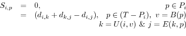
![\includegraphics[width=\columnwidth]{fig-data-path-v2}](img3.png)
|
In the proposed design, the external routers connected to a PoP are made to peer with the PoP's route-reflector. This is necessary since the external peer may be advertising the entire DFZ routing table and we don't want all these routes to reside on any given data-plane router. The route-reflector also has iBGP peerings with other route-reflectors and with the routers in its PoP. Egress filters are used on the route-reflector's peerings with the PoP's routers to ensure that a router only gets routes for the prefixes it is aggregating. This shrinks both the RIB and the FIB on the routers. The data-plane operation and hence, the path of packets through the ISP's network remains the same as with the previous design.
With this design, a PoP's route-reflector peers with all the external routers connected to the PoP. The RIB size on a BGP router depends on the number of peers it has and hence, the RIB for the route-reflectors can potentially be very large. If needed, the RIB requirements can be scaled by using multiple route-reflectors which may also be needed to provide customised routes to the PoP's neighbors. Note that the RIB scaling properties here are better than in the status quo. Today, edge routers have no choice but to peer with the directly connected external routers and maintain the resulting RIB. Replicating these routers is prohibitive because of their cost but the same does not apply to off-path route-reflectors, which could even be BGP software routers.
Design-II, apart from shrinking the RIB on the routers, does not require the route suppression feature on routers. Further, as we detail in section V-B, design-II reduces the ISP's route propagation time while the specific filtering mechanism used in design-I increases it. However, design-II does require the ISP's eBGP peerings to be reconfigured which, while straightforward, violates our goal of not impacting neighboring ISPs.
Past studies have shown that a large majority of Internet traffic is destined to a very small fraction of prefixes [34,10,13,38]. The fact that routers today have no choice but to maintain the complete DFZ routing table implies that this observation wasn't very useful for routing configuration. However, with ViAggre, individual routers only need to maintain routes for a fraction of prefixes. The ISP can thus configure its ViAggresuch that the small fraction of popular prefixes are in the FIB of every router and hence, are routed natively. For design-I, this involves configuring each router with a set of popular prefixes that should not be suppressed from the FIB. For design-II, a PoP's route-reflector can be configured to not filter advertisements for popular prefixes from the PoP's routers. Beyond this, the ISP may also choose to install customer prefixes into its routers such that they don't incur any stretch. The rest of the proposal involving virtual prefixesthe same and ensures that individual routers only maintain routes for a fraction of the unpopular prefixes. In section IV-B.4, we analyze Netflow data from a tier-1 ISP network to show that not only such an approach is feasible, it also addresses all the concerns raised above.
- ``BelongsTo''
relation B: T
![]() V such
that B(
V such
that B(![]() )=
)=![]() if prefix
if prefix ![]() belongs to or is
encompassed by virtual prefix
belongs to or is
encompassed by virtual prefix![]() .
.
- ``Egress'' relation E: R x
T
![]() R such that E(
R such that E(![]() ,
, ![]() )=
)=![]() if
traffic to prefix
if
traffic to prefix ![]() from router
from router ![]() egresses at router
egresses at router ![]() .
.
The mapping relation A: R
![]() 2
2![]() captures how the ISP assigns aggregation points; i.e. A(
captures how the ISP assigns aggregation points; i.e. A(![]() ) = {
) = {
![]() } implies that router
} implies that router ![]() aggregates virtual prefixes{
aggregates virtual prefixes{
![]() }. Given this assignment, we can determine the aggregation pointrouter
uses for its traffic to each virtual prefix.
This is captured by the ``Use'' relation U: R
x V
}. Given this assignment, we can determine the aggregation pointrouter
uses for its traffic to each virtual prefix.
This is captured by the ``Use'' relation U: R
x V
![]() R where U(
R where U(![]() ,
,
![]() ) =
) = ![]() or router
or router ![]() uses aggregation point
uses aggregation point![]() for virtual prefix
for virtual prefix![]() if the following conditions are satisfied:
if the following conditions are satisfied:
Here, condition 1) ensures that router
Using this notation, we can express the FIB size on routers and the stretch imposed on traffic.
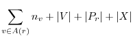 |
The Worst FIB size and the Average FIB size are
defined as follows:
 |
If router
2 Traffic Stretch
![]() uses router
uses router ![]() as an aggregation pointvirtual prefix
as an aggregation pointvirtual prefix![]() , packets from router
, packets from router ![]() to a prefix
to a prefix ![]() belonging to
belonging to ![]() are routed through router
are routed through router ![]() .
Hence, the stretch (S)
imposed on traffic to prefix
.
Hence, the stretch (S)
imposed on traffic to prefix ![]() from router
from router ![]() is given by:
is given by:
The Worst Stretch and Average Stretch are defined as follows:
 |
Problem: ViAggre, through the use of aggregation points, trades off an increase in path length for a reduction in routing state. The ISP can use the assignment of aggregation pointsa knob to tune this trade-off. Here we consider the simple goal of minimising the FIB Size on the ISP's routers while bounding the stretch. Specifically, the ISP needs to assign aggregation points by determining a mapping A that
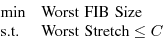
where C is the specified constraint on Worst Stretch. Note that much more complex formulations are possible. Our focus on worst-case metrics is guided by practical concerns - the Worst FIB Size dictates how the ISP's routers need to be provisioned while the Worst Stretch characterizes the most unfavorable impact of the use of ViAggre. Specifically, bounding the Worst Stretch allows the ISP to ensure that its existing SLAs are not breached and applications sensitive to increase in latency (example, VOIP) are not adversely affected.
The problem of assigning aggregation pointssatisfying the conditions
above can be mapped to the MultiCommodity Facility Location (MCL)
problem [33].
MCL is NP-hard
and [33] presents a logarithmic approximation
algorithm for it. Here we discuss a greedy approximation solution
to the problem, similar to the algorithm in [25].
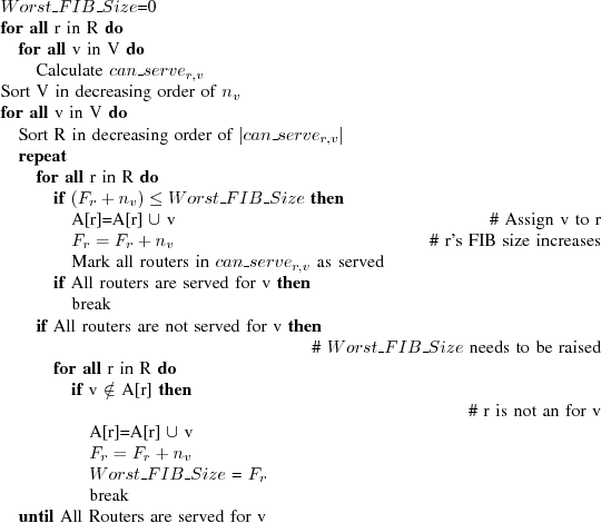
2 A Greedy Solution
The first solution step is to determine that if router ![]() were
to aggregate virtual prefix
were
to aggregate virtual prefix![]() , which routers can it serve
without violating the stretch constraint. This is the
, which routers can it serve
without violating the stretch constraint. This is the
![]() set and is defined as follows:
set and is defined as follows:
Given this, the key idea behind the solution is that any assignment based on the
Apart from the stretch imposed, another aspect of ViAggre's impact is the amount of traffic affected. To account for this, we define traffic impacted as the fraction of the ISP's traffic that uses a different router-level path than the native path. Note that in many cases, a router will use an aggregation pointthe destination virtual prefixthe same PoP and hence, the packets will follow the same PoP-level path as before. Thus, another metric of interest is the traffic stretched, the fraction of traffic that is forwarded along a different PoP-level path than before. In effect, this represents the change in the distribution of traffic across the ISP's inter-PoP links and hence, captures how ViAggrewith the ISP's inter-PoP traffic engineering.
The extra hops traversed by traffic increases the traffic load on the ISP's
routers. We define the load increase across a router as the extra traffic
it needs to forward due to ViAggre, as a fraction of the traffic
it forwards natively.
2 Impact on Router Load
We analysed the application of ViAggre
to a large tier-1 ISP in the Internet.
For our study, we obtained the ISP's router-level topology
(to determine router set R) and the routing tables of routers
(to determine prefix set T and the Egress E and BelongsTo
B relations). We used information about the
geographical locations of the routers to determine the Distance
matrix D such that
2 Tier-1 ISP Study
![]() is 0 if routers
is 0 if routers ![]() and
and ![]() belong to the same PoP (and hence, are in the same city) else
belong to the same PoP (and hence, are in the same city) else ![]() is
set to the propagation latency corresponding to the great circle
distance between
is
set to the propagation latency corresponding to the great circle
distance between ![]() and
and ![]() .
Further, we did not have information about the ISP's link
weights. However, guided by the fact that intra-domain traffic
engineering is typically
latency-driven [36], we
use the Distance matrix D as the Weight
matrix W. We also obtained the ISP's traffic matrix;
however, in order
to characterise the impact of vanilla ViAggre,
the first part of this section assumes that the ISP
does not consider any prefixes as popular.
.
Further, we did not have information about the ISP's link
weights. However, guided by the fact that intra-domain traffic
engineering is typically
latency-driven [36], we
use the Distance matrix D as the Weight
matrix W. We also obtained the ISP's traffic matrix;
however, in order
to characterise the impact of vanilla ViAggre,
the first part of this section assumes that the ISP
does not consider any prefixes as popular.
The ISP, in order to adopt ViAggre, needs to decide what virtual prefixesuse and which
routers aggregate these virtual prefixes. We describe the approaches we
evaluated.
1 Deployment decisions
- Determining set V. The most straightforward way to select virtual prefixessatisfying the two conditions specified in section II is to choose large prefixes (/6s, /7s, etc.) as virtual prefixes. We assume that the ISP uses /7s as its virtual prefixesrefer to this as the ``/7 allocation''.
However, such selection of virtual prefixeslead to a skewed distribution of (real) prefixes across them with some virtual prefixesa large number of prefixes. For instance, using /7s as virtual prefixes that the largest virtual prefix(202.0.0.0/7) contains 22,772 of the prefixes in today's BGP routing table or 8.9% of the routing table. Since at least one ISP router needs to aggregate each virtual prefix, such large virtual prefixesinhibit the ISP's ability to reduce the Worst FIB size on its routers. However, as we mentioned earlier, the virtual prefixesnot be of the same length and so large virtual prefixesbe split to yield smaller virtual prefixes. To study the effectiveness of this approach, we started with /7s as virtual prefixes split each of them such that the resulting virtual prefixesstill larger than any prefix in the Internet routing table. This yielded 1024 virtual prefixesthe largest containing 4,551 prefixes or 1.78% of the BGP routing table. We also use this virtual prefixfor our evaluation and refer to it as ``Uniform''.
- Determining mapping A. We implemented the algorithm described in section III-B and use it to designate routers to aggregate virtual prefixes.
We first look at the size and the composition of the FIB on the
ISP's routers with a ViAggre. Specifically, we focus on
the router with the largest FIB for a deployment where the
worst-case stretch (
2 Router FIB
![]() ) is constrained to 4ms. The first two
bars in figure 2 show the FIB composition for a /7
and uniform allocation respectively. With a /7
allocation, the router's FIB contains 46,543 entries which
represents 18.2% of the routing table today. This includes
22,772 prefixes,
128 virtual prefixes, 23,643 LSP mappings and 0 popular prefixes. As can
be seen, in both cases, the LSP mappings for tunnels to the
external routers contribute significantly to the FIB. This is
because the ISP has a large number of customer routers that it
has peerings with.
) is constrained to 4ms. The first two
bars in figure 2 show the FIB composition for a /7
and uniform allocation respectively. With a /7
allocation, the router's FIB contains 46,543 entries which
represents 18.2% of the routing table today. This includes
22,772 prefixes,
128 virtual prefixes, 23,643 LSP mappings and 0 popular prefixes. As can
be seen, in both cases, the LSP mappings for tunnels to the
external routers contribute significantly to the FIB. This is
because the ISP has a large number of customer routers that it
has peerings with.
However, we also note that customer ISPs do not advertise the full routing table to their provider. Hence, edge routers of the ISP could maintain routes advertised by customer routers in their FIB, advertise these routes onwards with themselves as the BGP NEXT_HOP and only initiate LSP advertisements for themselves and for peer and provider routers connected to them. With such a scheme, the number of LSP mappings that the ISP's routers need to maintain and the MPLS overhead in general reduces significantly. The latter set of bars in figure 2 shows the FIB composition with such a deployment for the router with the largest FIB. For the /7 allocation, the Worst FIB size is 23,101 entries (9.02% of today's routing table) while for the Uniform allocation, it is 10,226 entries (4.47%). In the rest of this section, we assume this model of deployment.
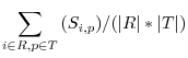
3 Stretch Vs. FIB Size
We ran the assignment algorithm with Worst Stretch Constraint
(C) ranging from 0 to 10 ms and determined the
(Average and Worst) Stretch and FIB Size of the resulting ViAggre
deployment. Figure 3(a) plots these metrics for the /7
allocation. The Worst FIB size, shown as a fraction of the
DFZ routing table size today, expectedly reduces as the constraint on Worst
Stretch is relaxed. However, beyond C=4ms, the Worst
FIB Size remains constant. This is because the largest virtual prefixa
/7 allocation encompasses 8.9% of the DFZ routing table and the
Worst FIB Size cannot be any less than
9.02% (0.12% overhead is due to virtual prefixesLSP mappings).
Figure 3(b) plots the same metrics for the Uniform allocation
and shows that the FIB can be shrunk even more.
The figure also shows that the Average FIB Size and the Average
stretch are expectedly small throughout. The anomaly beyond
C=8msec in figure 3(b) results from the fact that our assignment
algorithm is an approximation that can yield non-optimal results.
[With /7 allocation]![\includegraphics[width=0.9\columnwidth]{att-v2-savings-and-stretch-v1.eps}](img37.png) [With Uniform allocation]
[With Uniform allocation]![\includegraphics[width=0.9\columnwidth]{att-v2-savings-and-stretch-v2.eps}](img38.png)
For ViAggre, relaxing the worst-case stretch constraints reduces FIB size and hence, extends the router life. The table shows that if the DFZ routing table were to grow at the aforementioned exponential rate, ViAggreextend the life of the previous generation of routers to 2018 with no stretch at all. We realise that estimates beyond a few years are not very relevant since the ISP would need to upgrade its routers for other reasons such as newer technologies and higher data rates anyway. However, with ViAggre, at least the ISP is not forced to upgrade due to growth in the routing table.
Figure 4 plots the impact of
ViAggrethe ISP's traffic and router load. The percentage of traffic stretched
is small, less than 1% for C
![\includegraphics[width=0.9\columnwidth]{att-v2-traffic-nopopular-v2.eps}](img39.png)
![]() 6 ms. This shows that almost all the traffic is routed
through an aggregation pointthe same PoP as the ingress. However, the fact
that no prefixes are considered popular implies that almost all
the traffic follows a different router-level path as compared to
the status quo. This shows up in figure 4
since the traffic impacted is
6 ms. This shows that almost all the traffic is routed
through an aggregation pointthe same PoP as the ingress. However, the fact
that no prefixes are considered popular implies that almost all
the traffic follows a different router-level path as compared to
the status quo. This shows up in figure 4
since the traffic impacted is ![]() 100% throughout.
This, in turn, results in a median increase in load across the
routers by
100% throughout.
This, in turn, results in a median increase in load across the
routers by ![]() 39%. In the next section we discuss how an
ISP can use the skewed distribution of traffic to address the
load concern while maintaining a small FIB on its routers.
39%. In the next section we discuss how an
ISP can use the skewed distribution of traffic to address the
load concern while maintaining a small FIB on its routers.
Past studies of ISP traffic patterns from as early as 1999 have observed that a small
fraction of Internet prefixes carry a large majority of ISP
traffic [34,10,13,38]. We used Netflow records
collected across the routers of the same tier-1 ISP as in the
last section for a period of two months (20
4 Popular Prefixes
![]() Nov'07 to
20
Nov'07 to
20![]() Jan'07) to generate per-prefix traffic statistics and
observed that this pattern continues to the present day. The line labeled ``Day-based, ISP-wide'' in
figure 5 plots the average fraction of the ISP's traffic
destined to a given fraction of popular prefixes when the set of
popular prefixes is calculated across the ISP on a daily basis.
The figure shows that
1.5% of most popular prefixes carry 75.5% of the traffic while
5% of the prefixes carry 90.2% of the traffic.
Jan'07) to generate per-prefix traffic statistics and
observed that this pattern continues to the present day. The line labeled ``Day-based, ISP-wide'' in
figure 5 plots the average fraction of the ISP's traffic
destined to a given fraction of popular prefixes when the set of
popular prefixes is calculated across the ISP on a daily basis.
The figure shows that
1.5% of most popular prefixes carry 75.5% of the traffic while
5% of the prefixes carry 90.2% of the traffic.
ViAggrethe notion of prefix popularity to reduce its impact on the ISP's traffic. However, the ISP's routers need not consider the same set of prefixes as popular; instead the popular prefixes can be chosen per-PoP or even per-router. We calculated the fraction of traffic carried by popular prefixes, when popularity is calculated separately for each PoP on a daily basis. This is plotted in the figure as ``Day-based, per-PoP'' and the fractions are even higher.
When using prefix popularity for router configuration, it would be preferable to be able to calculate the popular prefixes over a week, month, or even longer durations. The line labeled ``Estimate, per-PoP'' in the figure shows the amount of traffic carried to prefixes that are popular on a given day over the period of the next month, averaged over each day in the first month of our study. As can be seen, the estimate based on prefixes popular on any given day carries just a little less traffic as when the prefix popularity is calculated daily. This suggests that prefix popularity is stable enough for ViAggreand the ISP can use the prefixes that are popular on a given day for a month or so. However, we admit that that these results are very preliminary and we need to study ISP traffic patterns over a longer period to substantiate the claims made above.
5 Load Analysis
We now consider the impact of a ViAggreinvolving popular
prefixes, i.e. the ISP populates the FIB on its routers with popular
prefixes. Specifically, we focus on a deployment wherein the aggregation points
are assigned to constrain Worst Stretch to 4ms, i.e. C
= 4ms.
Figure 6 shows how the traffic impacted and the
quartiles for the load increase vary with the percentage of
popular prefixes for both allocations. Note that using popular
prefixes increases the router FIB size by the number of
prefixes considered popular and thus, the upper X-axis in the
figure shows the Worst FIB size. The large fraction of traffic
carried by popular prefixes implies that both the traffic
impacted and the load increase drops sharply even when a
small fraction of prefixes is considered popular. For instance,
with 2% popular prefixes in case of the uniform allocation
(figure 6(b)), 7% of the traffic follows a
different router-level path than before while the
largest load increase is 3.1% of the original router
load. With 5% popular prefixes, the largest load increase is
1.38%. Note that the more even distribution of prefixes across
virtual prefixesthe uniform allocation results in a more even distribution
of the excess traffic load across the ISP's routers - this
shows up in the load quartiles being much smaller in
figure 6(b) as compared to the ones in
figure 6(a).
![]() =4ms.[With /7 allocation]
=4ms.[With /7 allocation]![\includegraphics[width=0.9\columnwidth]{att-v2-load-increase-v1.eps}](img44.png) [With Uniform allocation]
[With Uniform allocation]![\includegraphics[width=0.9\columnwidth]{att-v2-load-increase-v2.eps}](img45.png)
We studied the topologies of 10 ISPs collected as part of the
Rocketfuel project [37] to determine the
FIB size savings that ViAggreyield.
Note that the fact we
don't have traffic matrices for these ISPs implies that we cannot
analyze the load increase across their routers. For each ISP, we used the
assignment algorithm to
determine the worst FIB size resulting from a ViAggre
where the worst stretch is limited to 5ms.
Figure 7 shows that the worst FIB
size is always less than 15% of the DFZ routing table.
However, the Rocketfuel topologies are not complete and
are missing routers. Hence,
while the results presented here are encouraging, they should be
treated as conservative estimates of the savings that ViAggreyield for
these ISPs.
3 Rocketfuel Study
The analysis above shows that ViAggresignificantly reduce FIB size.
Most of the ISPs we studied are large tier-1 and tier-2 ISPs. However,
smaller tier-2 and tier-3 ISPs are also part of the Internet DFZ.
Actually, it is probably more important for such ISPs to be able
to operate without needing to upgrade to the latest generation of
routers.
The fact that these ISPs have small PoPs might suggest
that ViAggrenot be very beneficial. However, given their small
size, the PoPs of these ISPs are typically geographically close
to each other. Hence, it is possible to use the cumulative FIB
space across routers of close-by PoPs to shrink the FIB
substantially. And the use of popular prefixes ensures that the
load increase and the traffic impact is still small.
For instance, we analyzed router topology and
routing table data from a regional tier-2 ISP (AS2497) and found
that a ViAggrewith worst stretch less than 5ms can shrink
the Worst FIB size to 14.2% of the routing table today.
4 Discussion
Further, the fact that such ISPs are not tier-1 ISPs implies they are a customer of at least one other ISP. Hence, in many cases, the ISP could substantially shrink the FIB size on its routers by applying ViAggrethe small number of prefixes advertised by their customers and peers while using default routes for the rest of the prefixes.
![\includegraphics[width=0.9\columnwidth]{fig-wail-v1}](img47.png)
|
For the ViAggre, we use
two virtual prefixes: 0.0.0.0/1
(VP1) and 128.0.0.0/1 (VP2) with one router in each PoP serving as
an aggregation pointeach virtual prefix.
Routers R1 and R4 have an external router connected to them and
exchange routes using an eBGP peering. Specifically, router R5
advertises the entire DFZ routing table and this is, in turn,
advertised through the ISP to router R6. We use OSPF for
intra-domain routing. Beyond this, we configure the internal
distribution of BGP routes according to the following three
approaches:
1). Status Quo. The routers use a mesh of iBGP peerings to exchange the routes and hence, each router maintains the entire routing table.
2). Design-I. The routers still use a mesh of iBGP peerings to exchange routes. Beyond this, the routers are configured as follows:
- Virtual Prefixes. Routers advertise the virtual prefixare aggregating to their iBGP peers.
- FIB Suppression. Each router only loads the routes that it is aggregating into its FIB. For instance, router R1 uses an access-list to specify that only routes belonging to VP1, the virtual prefix2 itself and any popular prefixes are loaded into the FIB. A snippet of this access-list is shown below.
! R5's IP address is 198.18.1.200
distance 255 198.18.1.200 0.0.0.0 1
! Don't mark anything inside 0.0.0.0/1
access-list 1 deny 0.0.0.0 128.255.255.255
! Don't mark virtual prefix128.0.0.0/1
access-list 1 deny 0.0.0.0 128.0.0.0
! Don't mark popular prefix 122.1.1.0/24
access-list 1 deny 122.1.1.0 0.0.0.255
! ... other popular prefixes follow ...
! Mark the rest with admin distance 255
access-list 1 permit any
Here, the distance command sets the administrative distance of all prefixes that are accepted by access-list 1 to ``255'' and these routes are not loaded by the router into its FIB.
- LSPs to external routers. We use MPLS for the tunnels between routers. To this effect, LDP [1] is enabled on the interfaces of all routers and establishes LSPs between the routers. Further, each edge router (R1 and R4) initiates a Downstream Unsolicited tunnel [1] for each external router connected to them to all their IGP neighbors using LDP. This ensures that packets to an external router are forwarded using MPLS to the edge router which strips the MPLS header before forwarding them onwards.
Given this setup and assuming no popular prefixes, routers R1 and R3 store 40.9% of today's routing table (107,943 prefixes that are in VP1) while R2 and R4 store 59.1%.
3). Design-II. The routers in a PoP peer with the route-reflector of the PoP and the route-reflectors peer with each other. External routers R1 and R6 are reconfigured to have eBGP peerings with RR1 and RR2 respectively. The advertisement of virtual prefixesthe MPLS configuration is the same as above. Beyond this, the route-reflectors are configured to ensure that they only advertise the prefixes being aggregated by a router to it. For instance, RR1 uses a prefix-list to ensure that only prefixes belonging to VP1, virtual prefix2 itself and popular prefixes are advertised to router R1. The structure of this prefix-list is similar to the access-list shown above. Finally, route-reflectors use a route-map on their eBGP peerings to change the BGP NEXT_HOP of the advertised routes to the edge router that the external peer is connected too. This ensures that the packets don't actually flow through the route-reflectors.
A drawback of ViAggrea ``configuration-only'' approach is the
overhead that the extra configuration entails. The discussion
above details the extra configuration that routers need to
participate in ViAggre. Based on our deployment, the number of extra
configuration lines needed for a router
1 Configuration Overhead
![]() to be configured
according to design-I is given by (
to be configured
according to design-I is given by (
![]() ) where
) where ![]() is the number of router interfaces,
is the number of router interfaces,
![]() is the number of external routers
is the number of external routers ![]() is peering with,
is peering with,
![]() is the number of virtual prefixes
is the number of virtual prefixes![]() is aggregating and
is aggregating and ![]() is the number of popular prefixes in
is the number of popular prefixes in ![]() . Given the size of the
routing table today, considering even a small fraction of
prefixes as popular would cause the expression to be dominated by
. Given the size of the
routing table today, considering even a small fraction of
prefixes as popular would cause the expression to be dominated by
![]() and can represent a large number of configuration
lines.
and can represent a large number of configuration
lines.
However, quantifying the extra configuration lines does not paint the complete picture since given a list of popular prefixes, it is trivial to generate an access or prefix-list that would allow them. To illustrate this, we developed a configuration tool as part of our deployment effort. The tool is 334 line python script which takes as input a router's existing configuration file, the list of virtual prefixes, the router's (or representative) Netflow records and the percentage of prefixes to be considered popular. The tool extracts relevant information, such as information about the router's interfaces and peerings, from the configuration file. It also uses the Netflow records to determine the list of prefixes to be considered popular. Based on these extracted details, the script generates a configuration file that allows the router to operate as a ViAggre. We have been using this tool for experiments with our deployment. Further, we use clogin [41] to automatically load the generated ViAggrefile onto the router. Thus, we can reconfigure our testbed from status quo operation to ViAggre operation (design-I and design II) in an automated fashion. While our tool is specific to the router vendor and other technologies in our deployment, its simplicity and our experience with it lends evidence to the argument that ViAggrea good trade-off between the configuration overhead and increased routing scalability.
Section IV evaluated the impact of ViAggrethe ISP's
data plane.
Beyond this, ViAggrecontrol-plane mechanisms to divide the
routing table amongst the ISP's routers - Design-I uses
access-lists
and Design-II uses prefix-lists.
We quantify the
performance overhead imposed by these mechanisms using our
deployment. Specifically, we look at the impact of our designs on
the propagation of routes through the ISP.
2 Control-plane Overhead
![\includegraphics[width=0.9\columnwidth]{time-v2.eps}](img53.png)
[Status Quo, Measured on R1]![\includegraphics[width=0.9\columnwidth]{quo-v1.eps}](img54.png)
[Design-I, 2% PP, Measured on R1]![\includegraphics[width=0.9\columnwidth]{d1p2-cpu-v1.eps}](img55.png)
[Design-I, 5% PP, Measured on R1]![\includegraphics[width=0.9\columnwidth]{d1p5-cpu-v1.eps}](img56.png)
[Design-II, 2% PP, Measured on RR1]![\includegraphics[width=0.9\columnwidth]{d2p2-cpu-v1.eps}](img57.png)
[Design-II, 5% PP, Measured on RR1]![\includegraphics[width=0.9\columnwidth]{d2p5-cpu-v1.eps}](img58.png)
To this effect, we configured the internal distribution of BGP routes in our testbed according to the three approaches described above. External router R5 is configured to advertise a variable number of prefixes through its eBGP peering. We restart this peering on router R5 and measure the time it takes for the routes to be installed into the FIB of the ISP's routers and then advertised onwards; hereon we refer to this as the installation time. During this time, we also measure the CPU utilization on the routers. We achieve this by using a clogin script to execute the ``show process cpu'' command on each router every 5 seconds. The command gives the average CPU utilization of individual processes on the router over the past 5 seconds and we extract the CPU utilization of the ``BGP router'' process.
We measured the installation time and the CPU utilization for the three approaches. For status quo and design-I, we focus on the measurements for router R1 while for design-II, we focus on the measurements for route-reflector RR1. We also varied the number of popular prefixes. Here we present results with 2% and 5% popular prefixes. Figures 9 and 10 plot the installation time and the quartiles for the CPU utilization respectively.
Design-I Vs Status Quo. Figure 9 shows that the installation time with design-I is much higher than that with status quo. For instance, with status quo, the complete routing table is transferred and installed on router R1 in 273 seconds while with design-I and 2% popular prefixes, it takes 487 seconds. Further, the design-I installation time increases significantly as the number of popular prefixes increases. Finally, figures 10(b) and 10(c) show that design-I leads to a very high CPU load during the transfer which increases as more prefixes are considered popular. This results from the fact that access-lists with a large number of rules are very inefficient and would obviously be unacceptable for an ISP deploying ViAggre. We are currently exploring ways to achieve FIB suppression without the use of access-list.
Design-II Vs Status Quo. Figure 9 shows that the time to transfer, install and propagate routes with design-II is lesser than status quo. For instance, design-II with 2% popular prefixes leads to an installation time of 124 seconds for the entire routing table as compared to 273 seconds for status quo. Further, the installation time does not change much as the fraction of popular prefixes increases. Figures 10(d) and 10(e) show that the CPU utilization is low with median utilization being less than 20%. Note that the utilization shown for design-II was measured on route-reflector RR1 which has fewer peerings than router R1 in status quo. This explains the fact that the utilization with design-II is less than status quo. While preliminary, this experiment suggests that design-II can also help with route convergence within the ISP.
As detailed in section II-E, as long as alternate
aggregation points, traffic in a ViAggreis automatically re-routed
upon failure of the aggregation pointused. We measured this failover
time using our testbed. In the interest of space, we very briefly
summarise the experiment here. We generated UDP traffic between PCs
connected to routers R5 and R6 (figure 8) and then
crashed the router being used as the aggregation pointthe traffic.
We measured the time it takes for traffic to be re-routed over 10
runs with each design. In both cases, the maximum observed
failover time was 200 usecs.
This shows that
our designs ensure fast failover between aggregation points.
3 Failover
Pros. ViAggrebe incrementally deployed by an ISP since it does not require the
cooperation of other ISPs and router vendors.
The ISP does not
need to change the structure of its PoPs or its topology.
What's more, an ISP could experiment with ViAggrea limited scale
(a few virtual prefixesa limited number of PoPs) to gain experience and
comfort before expanding its deployment.
None of the attributes in the BGP routes advertised by the ISP to
its neighbors are changed due to the adoption of ViAggre.
Also, the use of ViAggre
by the ISP does not restrict its routing policies and route
selection.
Further, at least for design-II, control-plane processing is
reduced.
Finally,
there is incentive for deployment since the ISP improves
its own capability to deal with routing table growth.
6 Discussion
Management Overhead. As detailed in section V-A, ViAggreextra configuration on the ISP's routers. Beyond this, the ISP needs to make a number of deployment decisions such as choosing the virtual prefixesuse, deciding where to keep aggregation pointseach virtual prefix, and so on. Apart from such one-time or infrequent decisions, ViAggrealso influence very important aspects of the ISP's day-to-day operation such as maintenance, debugging, etc. All this leads to increased complexity and there is a cost associated with the extra management.
In section V-A we discussed a configuration tool that automates ViAggre. It is difficult to speculate about actual costs and so we don't compare the increase in management costs against the cost of upgrading routers. While we hope that our tools will actually lead to cost savings for a ViAggre, an ISP might just be inclined to adopt ViAggre because it breaks the dependency of various aspects of its operation on the size of the routing table. These aspects include its upgrade cycle, the per-byte forwarding cost, the per-byte forwarding power, etc.
Popular Prefixes. As mentioned earlier, ViAggrea trade-off between FIB shrinkage on one hand and increased router load and traffic stretch on the other. The fact that Internet traffic follows a power-law distribution makes this a very beneficial trade-off. This power-law observation has held up in measurement studies from 1999 [10] to 2008 (in this paper) and hence, Internet traffic has followed this distribution for at least the past nine years in spite of the rise in popularity of P2P and video streaming. We believe that, more likely than not, future Internet traffic will be power-law distributed and hence, ViAggrerepresent a good trade-off for ISPs.
Other design points. The ViAggrepresented in this paper represents one point in the design space that we focussed on for the sake of concreteness. Alternative approaches based on the same idea include
- Adding routers. We have presented a couple of techniques that ensure that only a subset of the routing table is loaded into the FIB. Given this, an ISP could install ``slow-fat routers'', low-end devices (or maybe even a stack of software routers [16]) in each PoP that are only responsible for routing traffic destined to unpopular prefixes. These devices forward a low-volume of traffic, so it would be easier and cheaper to hold the entire routing table. The popular prefixes are loaded into existing routers. This approach can be seen as a variant of route caching and does away with a lot of deployment complexity. In fact, ViAggre allow us to revisit route caching [24].
- Router changes. Routers can be changed to be ViAggre-aware and hence, make virtual prefixes-class network objects. This would do away with a lot of the configuration complexity that ViAggre, ensure that ISPs get vendor support and hence, make it more palatable for ISPs. We, in cooperation with a router vendor, are exploring this option [15].
- Clean-slate ViAggre. The basic concept of virtual networksbe applied in an inter-domain fashion. The idea here is to use cooperation amongst ISPs to induce a routing hierarchy that is more aggregatable and hence, can accrue benefits beyond shrinking the router FIB. This involves virtual networks for individual virtual prefixesdomains such that even the RIB on a router only contains the prefixes it is responsible for. This would reduce both the router FIB and RIB and in general, improve routing scalability. We intend to study the merits and demerits of such an approach in future work.
A number of efforts have tried to directly tackle the routing scalability problem through clean-slate designs. One set of approaches try to reduce routing table size by dividing edge networks and ISPs into separate address spaces [7,11,32,29,40]. Our work resembles some aspects of CRIO [40] which uses virtual prefixes and tunneling to decouple network topology from addressing. However, CRIO requires adoption by all provider networks and like [7,11,32,29], requires a new mapping service to determine tunnel endpoints. APT [22] presents such a mapping service. Alternatively, it is possible to encode location information into IP addresses [14,8,18] and hence, reduce routing table size. Finally, an interesting set of approaches that trade-off stretch for routing table size are Compact Routing algorithms; see [26] for a survey of the area.
The use of tunnels has long been proposed as a routing scaling mechanism. VPN technologies such as BGP-MPLS VPNs [9] use tunnels to ensure that only PE routers need to keep the VPN routes. As a matter of fact, ISPs can and probably do use tunneling protocols such as MPLS and RSVP-TE to engineer a BGP-free core [35]. However, edge routers still need to keep the full FIB. With ViAggre, none of the routers on the data-path need to maintain the full FIB. Router vendors, if willing, can use a number of techniques to reduce the FIB size, including FIB compression [35] and route caching [35]. Forgetful routing [23] selectively discards alternative routes to reduce RIB size. [2] sketches the basic ViAggre. In recent work, Kim et. al. [25] use relaying, similar to ViAggre's use of aggregation points, to address the VPN routing scalability problem.
Over the years, several articles have documented the existing state of inter-domain routing and delineated requirements for the future [5,12,28]; see [12] for other routing related proposals. RCP [4] and 4D [17] argue for logical centralization of routing in ISPs to provide scalable internal route distribution and a simplified control plane respectively. We note that ViAggrewell into these alternative routing models. As a matter of fact, the use of route-reflectors in design-II is similar in spirit to RCSs in [4] and DEs in [17].
This paper presents ViAggre, a technique that can be used by an ISP
to substantially shrink the
FIB on its routers and hence, extend the lifetime of its
installed router base. The ISP may have to upgrade the routers
for other reasons but at least it is not driven by DFZ growth
over which it has no control. While it remains to be seen whether
the use of automated tools to configure and manage large ViAggre
can offset the complexity concerns,
we believe that the simplicity of the proposal and its possible short-term impact on
routing scalability suggest that is an alternative worth
considering.
8 Summary
![\includegraphics[width=0.9\columnwidth]{att-fib-fraction-v1.eps}](img36.png)
![\includegraphics[width=\columnwidth]{popular-prefix-v3}](img43.png)
![\includegraphics[width=\columnwidth]{savings-v3}](img46.png)