Harnessing Exposed Terminals in Wireless Networks
Mythili Vutukuru, Kyle Jamieson, and Hari Balakrishnan
MIT Computer Science and Artificial Intelligence Laboratory
{mythili , jamieson , hari}@csail.mit.edu
Abstract
This paper presents the design, implementation, and experimental
evaluation of CMAP (Conflict Maps), a system that increases the
number of successful concurrent transmissions in a wireless network,
achieving higher aggregate throughput compared to networks that use
carrier sense multiple access (CSMA).
CMAP correctly identifies and exploits exposed terminals in
which two senders are within range of one another, but each intended
receiver is far enough from the other sender that the two
transmissions can succeed even if done concurrently. CMAP includes
a reactive channel access scheme in which nodes transmit
concurrently (even if there's the possibility of a collision), then
observe the loss probability to determine whether they are better
off transmitting concurrently or not. Experimental results from a
50-node 802.11a testbed show that CMAP improves throughput by
2× over CSMA with exposed terminals, while converging to the
performance of CSMA when the senders and receivers are all close to
each other. CMAP also improves throughput by up to 47% over CSMA
in realistic access point-based networks by exploiting concurrent
transmission opportunities.
1 Introduction
It is well-known that maximizing the number of successful concurrent
transmissions is a good way to maximize the aggregate throughput in a
wireless network. Current contention-based channel access protocols
generally attempt to minimize the number of packet collisions,
allowing concurrent transmissions only when the nodes determine that
they are unlikely to result in a collision. For example, in the
popular carrier sense multiple access (CSMA) scheme, before
transmitting, a sender listens to the channel and assesses whether a
nearby node is transmitting. If no nearby node is transmitting, the
sender transmits immediately. If a nearby node is transmitting, then
the sender defers, waiting for some time after the end of the on-going
transmission. Then the sender repeats the same carrier sense-defer
process.
 Figure 1: An example transmission from S to R with three
abstract sender cases: an in-range but conflicting sender CS,
an exposed sender ES, and a hidden sender HS.
Because a receiver's ability to decode a packet successfully depends
on channel conditions near the receiver and not the sender, CSMA
is at best a sender's crude guess about what the receiver
perceives. This guess can be correct if the receiver and sender are
close enough that they experience similar noise and interference
conditions. However, it can also prevent a sender (e.g., ES in
Figure 1) from transmitting a packet when its intended
destination has a lower level of noise and interference-an
exposed terminal situation. In addition, researchers have observed
that receivers can often "capture" packets from a transmission even
in the presence of interfering
transmissions [18,20], suggesting that
simply extending the carrier sense mechanism to the receiver does not
solve the problem. We argue that schemes like CSMA in which nodes use
heuristics (such as "carrier is busy") to perform channel access are
too conservative in exploiting concurrency because they are
"proactive": nodes defer to ongoing transmissions without knowing
whether in fact their transmission actually interferes with ongoing
transmissions.
To improve throughput in a wireless network, we propose CMAP , a
link-layer whose channel access scheme reactively and
empirically learns of transmission conflicts in the network. Nodes
optimistically assume that concurrent transmissions will succeed, and
carry them out in parallel. Then, in response to observed packet
loss, they discover which concurrent transmissions are likely to work,
and which aren't (probabilistically), dynamically building up a
distributed data structure containing a "map" of conflicting
transmissions (e.g., S to R and CS to CR in
Figure 1). In §3, we describe this novel
conflict map data structure (hence the name CMAP ), and show how
nodes can maintain it in a distributed fashion by overhearing ongoing
transmissions and exchanging lightweight information with their
one-hop neighbors. By listening to ongoing transmissions on the
shared medium to identify the current set of transmitters, and
consulting the conflict map just before it intends to transmit, each
node determines whether to transmit data immediately, or defer.
Of course, not all conflicting senders will be in range of each other
to overhear and make the transmit-or-defer decision because of the
well-known "hidden terminal" problem (HS in
Figure 1). To prevent performance degradation in such
cases, a CMAP sender implements a reactive loss-based backoff
mechanism to reduce its packet transmission rate in response to
receiver feedback about packet loss.
Finally, note that any scheme that seeks to exploit the exposed terminal
opportunity shown in Figure 1 must cope with
link-layer ACKs from R to S being lost at S due to a
collision with ES's transmission. CMAP tolerates ACK losses
with a windowed ACK and retransmission protocol.
We have implemented a CMAP prototype in software running on a 50-node
testbed with commodity 802.11a wireless LAN
hardware (§4). We present an evaluation of CMAP in
§5 showing that CMAP leads to a 2× improvement over
CSMA with exposed terminals, while successfully avoiding interfering
concurrent transmissions. In access point-based topologies with
multiple concurrent transmissions, CMAP improves aggregate throughput
by between 21% and 47%; the median per-source throughput is
1.8× better than CSMA. CMAP also achieves a 52% improvement in aggregate
throughput over CSMA in content dissemination mesh networks. These
gains are mainly due to the non-interfering concurrent transmission
opportunities that CMAP is able to exploit.
The contributions of this paper over existing proposals to solve the
exposed terminal problem [1,11,16] are as follows. First, CMAP identifies all
exposed terminal opportunities because it uses packet delivery
probabilities, not heuristics that may (indirectly) influence packet
delivery, to identify exposed terminals. Second, CMAP nodes gather
the packet delivery probabilities in an online and distributed
fashion, and do not require any offline measurements. Finally, CMAP
demonstrates its gains in a live 802.11a testbed implementation.
Figure 1: An example transmission from S to R with three
abstract sender cases: an in-range but conflicting sender CS,
an exposed sender ES, and a hidden sender HS.
Because a receiver's ability to decode a packet successfully depends
on channel conditions near the receiver and not the sender, CSMA
is at best a sender's crude guess about what the receiver
perceives. This guess can be correct if the receiver and sender are
close enough that they experience similar noise and interference
conditions. However, it can also prevent a sender (e.g., ES in
Figure 1) from transmitting a packet when its intended
destination has a lower level of noise and interference-an
exposed terminal situation. In addition, researchers have observed
that receivers can often "capture" packets from a transmission even
in the presence of interfering
transmissions [18,20], suggesting that
simply extending the carrier sense mechanism to the receiver does not
solve the problem. We argue that schemes like CSMA in which nodes use
heuristics (such as "carrier is busy") to perform channel access are
too conservative in exploiting concurrency because they are
"proactive": nodes defer to ongoing transmissions without knowing
whether in fact their transmission actually interferes with ongoing
transmissions.
To improve throughput in a wireless network, we propose CMAP , a
link-layer whose channel access scheme reactively and
empirically learns of transmission conflicts in the network. Nodes
optimistically assume that concurrent transmissions will succeed, and
carry them out in parallel. Then, in response to observed packet
loss, they discover which concurrent transmissions are likely to work,
and which aren't (probabilistically), dynamically building up a
distributed data structure containing a "map" of conflicting
transmissions (e.g., S to R and CS to CR in
Figure 1). In §3, we describe this novel
conflict map data structure (hence the name CMAP ), and show how
nodes can maintain it in a distributed fashion by overhearing ongoing
transmissions and exchanging lightweight information with their
one-hop neighbors. By listening to ongoing transmissions on the
shared medium to identify the current set of transmitters, and
consulting the conflict map just before it intends to transmit, each
node determines whether to transmit data immediately, or defer.
Of course, not all conflicting senders will be in range of each other
to overhear and make the transmit-or-defer decision because of the
well-known "hidden terminal" problem (HS in
Figure 1). To prevent performance degradation in such
cases, a CMAP sender implements a reactive loss-based backoff
mechanism to reduce its packet transmission rate in response to
receiver feedback about packet loss.
Finally, note that any scheme that seeks to exploit the exposed terminal
opportunity shown in Figure 1 must cope with
link-layer ACKs from R to S being lost at S due to a
collision with ES's transmission. CMAP tolerates ACK losses
with a windowed ACK and retransmission protocol.
We have implemented a CMAP prototype in software running on a 50-node
testbed with commodity 802.11a wireless LAN
hardware (§4). We present an evaluation of CMAP in
§5 showing that CMAP leads to a 2× improvement over
CSMA with exposed terminals, while successfully avoiding interfering
concurrent transmissions. In access point-based topologies with
multiple concurrent transmissions, CMAP improves aggregate throughput
by between 21% and 47%; the median per-source throughput is
1.8× better than CSMA. CMAP also achieves a 52% improvement in aggregate
throughput over CSMA in content dissemination mesh networks. These
gains are mainly due to the non-interfering concurrent transmission
opportunities that CMAP is able to exploit.
The contributions of this paper over existing proposals to solve the
exposed terminal problem [1,11,16] are as follows. First, CMAP identifies all
exposed terminal opportunities because it uses packet delivery
probabilities, not heuristics that may (indirectly) influence packet
delivery, to identify exposed terminals. Second, CMAP nodes gather
the packet delivery probabilities in an online and distributed
fashion, and do not require any offline measurements. Finally, CMAP
demonstrates its gains in a live 802.11a testbed implementation.
2 Overview of CMAP
The CMAP design has three parts: a channel access (MAC) protocol, a windowed
retransmission protocol, and a backoff mechanism that uses receiver feedback.
Channel access. The CMAP MAC uses a distributed data structure
called the conflict map, which allows nodes to determine which
pairs of transmissions are likely to obtain lower throughput if done
concurrently than if done sequentially. The nodes in the network use
empirical observations of packet losses to populate the conflict
map, rather than assuming proactively (e.g., because the carrier is
busy) that a given pair of transmissions shouldn't be done
concurrently because a collision might ensue.
 Figure 2: Example conflict map state shown for node u when it detects
a transmission between x and y that conflicts with its
transmission to v.
Each node computes and stores a portion of the conflict map using
feedback from its receivers about the fate of its transmissions. This
conflict information at node u is a table with entries of the form
(v: x → y). This entry, shown in Figure 2,
means that if u were to send to v concurrently with a transmission
from x to y, then the resulting throughput would be lower than if
the two transmissions were done sequentially. We call such
transmissions conflicting. If two transmissions conflict, it
would be better for one of the senders (say, u) to defer its
transmission while the other transmission is in progress. For this
reason, we call this table the node's defer table. The union of
the defer tables of all the nodes in the network forms its conflict
map.
Initially, the defer table at each node is empty, so nodes transmit
without hesitation whenever they have data to send. Each receiver
keeps track of the packet loss rates from its sender as well as what
other concurrent transmissions were ongoing during the time it was
receiving packets. If a receiver notices that the packet loss rate
from its sender is high when another concurrent transmission is in
progress, it infers that the concurrent transmissions conflict and
propagates this information to the defer tables of the conflicting
senders. §3.1 describes this process in detail.
Each node in the network continuously listens to the wireless channel
to keep track of what other transmissions are currently in progress in
its vicinity. When a node u is about to send a packet to node v,
it consults its defer table to see if there are any entries of the
form v: x → y, such that there's an ongoing transmission
between x and y. If so, u defers its transmission until x→ y completes and then re-attempts to transmit. Otherwise,
it goes ahead and transmits. The transmission decision process is
described in §3.2.
Windowed retransmission protocol. To increase the packet
success rate observed by higher layers, receivers send link-layer ACKs
for the received data packets; in response, the sender retransmits
packets presumed lost. The CMAP retransmission protocol
(§3.3) uses a window, unlike current wireless LAN link
layers that use a stop-and-wait retransmission protocol (i.e., a window
size of 1). The ACKs sent by receivers are cumulative and contain a
bitmap indicating which packets in the window have been received.
The main benefit of the window mechanism is to avoid spurious
retransmissions when only the ACK (and not the data packet) gets lost,
thereby making the retransmission protocol resilient to ACK losses.
This resilience is important for CMAP because although making
transmission decisions using the defer table exploits exposed terminal
opportunities, the ACKs have a high likelihood of being lost in
collisions at the exposed senders. For example, in
Figure 1, the ACK from receiver R to sender S
can collide at S with a data transmission from ES to
ER.
Backoff policy. As described thus far, for a sender to defer to
an interfering transmission, the receiver must be able to identify the
interferer and the sender must be able to overhear the interfering
transmission. Therefore, CMAP may degrade performance when an
interferer is out of hearing range of either the sender or the
receiver; we show in §5.4 that the expected
reduction in CMAP throughput due to such "hidden interferers" is
around 10% of the link rate. To improve throughput in such cases,
CMAP uses a loss rate-based backoff policy
(§3.4). Because CMAP uses cumulative ACKs, senders in
CMAP , unlike 802.11 senders, do not back off every time a transmission
fails to elicit an ACK. Instead, receivers report the loss rate over a
window of packets in every cumulative ACK, and senders back off when
this loss rate exceeds a threshold.
Figure 2: Example conflict map state shown for node u when it detects
a transmission between x and y that conflicts with its
transmission to v.
Each node computes and stores a portion of the conflict map using
feedback from its receivers about the fate of its transmissions. This
conflict information at node u is a table with entries of the form
(v: x → y). This entry, shown in Figure 2,
means that if u were to send to v concurrently with a transmission
from x to y, then the resulting throughput would be lower than if
the two transmissions were done sequentially. We call such
transmissions conflicting. If two transmissions conflict, it
would be better for one of the senders (say, u) to defer its
transmission while the other transmission is in progress. For this
reason, we call this table the node's defer table. The union of
the defer tables of all the nodes in the network forms its conflict
map.
Initially, the defer table at each node is empty, so nodes transmit
without hesitation whenever they have data to send. Each receiver
keeps track of the packet loss rates from its sender as well as what
other concurrent transmissions were ongoing during the time it was
receiving packets. If a receiver notices that the packet loss rate
from its sender is high when another concurrent transmission is in
progress, it infers that the concurrent transmissions conflict and
propagates this information to the defer tables of the conflicting
senders. §3.1 describes this process in detail.
Each node in the network continuously listens to the wireless channel
to keep track of what other transmissions are currently in progress in
its vicinity. When a node u is about to send a packet to node v,
it consults its defer table to see if there are any entries of the
form v: x → y, such that there's an ongoing transmission
between x and y. If so, u defers its transmission until x→ y completes and then re-attempts to transmit. Otherwise,
it goes ahead and transmits. The transmission decision process is
described in §3.2.
Windowed retransmission protocol. To increase the packet
success rate observed by higher layers, receivers send link-layer ACKs
for the received data packets; in response, the sender retransmits
packets presumed lost. The CMAP retransmission protocol
(§3.3) uses a window, unlike current wireless LAN link
layers that use a stop-and-wait retransmission protocol (i.e., a window
size of 1). The ACKs sent by receivers are cumulative and contain a
bitmap indicating which packets in the window have been received.
The main benefit of the window mechanism is to avoid spurious
retransmissions when only the ACK (and not the data packet) gets lost,
thereby making the retransmission protocol resilient to ACK losses.
This resilience is important for CMAP because although making
transmission decisions using the defer table exploits exposed terminal
opportunities, the ACKs have a high likelihood of being lost in
collisions at the exposed senders. For example, in
Figure 1, the ACK from receiver R to sender S
can collide at S with a data transmission from ES to
ER.
Backoff policy. As described thus far, for a sender to defer to
an interfering transmission, the receiver must be able to identify the
interferer and the sender must be able to overhear the interfering
transmission. Therefore, CMAP may degrade performance when an
interferer is out of hearing range of either the sender or the
receiver; we show in §5.4 that the expected
reduction in CMAP throughput due to such "hidden interferers" is
around 10% of the link rate. To improve throughput in such cases,
CMAP uses a loss rate-based backoff policy
(§3.4). Because CMAP uses cumulative ACKs, senders in
CMAP , unlike 802.11 senders, do not back off every time a transmission
fails to elicit an ACK. Instead, receivers report the loss rate over a
window of packets in every cumulative ACK, and senders back off when
this loss rate exceeds a threshold.
2.1 Physical Layer Abstraction
CMAP encapsulates packets with a CMAP header and trailer before
handing them over to the physical layer (PHY). We assume the
following abstract model of the underlying PHY: it decodes and
delivers the headers and trailers of received packets independent of the
rest of the packet [5]. This PHY model has two
important properties. First, it "streams" the header of an incoming
packet to the CMAP layer before the rest of the packet reception
completes. This property ensures that nodes learn of and defer to
ongoing conflicting transmissions in a timely manner. Second, even if
some bits in the packet's payload are corrupted in a transmission, the
PHY can salvage error-free headers and trailers and pass that
information to CMAP . This ability to recover headers or trailers from
a collision helps populate the conflict map (§3.1).
This abstract model of the physical layer can be realized in two ways.
Our CMAP implementation (§4) uses a software "shim"
that transmits separate small "header" and "trailer" packets with
their own checksums (CRCs) before and after a data packet
respectively; doing so provides the abstraction with the two
properties mentioned above without modifying the current PHY
implementations. An alternate approach, which requires hardware
modification but has lower overhead, is to transmit the header and
trailer as part of the packet and use recently-proposed partial packet
recovery techniques [5] to decode headers and
trailers independently. For ease of exposition and without loss of
generality, however, we will describe the design of CMAP assuming the
physical layer abstraction of the previous paragraph.
3 CMAP Design
 Figure 3: CMAP packet format.
This section describes CMAP 's design in detail. The CMAP packet
format, header and trailer subfields and their suggested sizes are
shown in Figure 3. In addition to the
source and destination MAC addresses, the CMAP header and trailer
contain the estimated transmission time of the packet, which lets
deferring nodes decide how long they need to wait before attempting to
send data. They also contain a link-layer sequence number and a
separate CRC covering the entire header or trailer.
CMAP nodes are always in promiscuous mode, attempting to decode the
headers and trailers of other concurrent transmissions that they can
overhear.
1
For now, we assume that all packets are transmitted at a common
bit-rate and power level. This assumption simplifies the discussion
of the system; in §3.5, we discuss how CMAP must be
modified to handle heterogeneous bit-rates and transmit power
levels. We also assume that all transmissions are unicast; we discuss
how to handle transmissions with more than one intended destination in
§3.6.
Figure 3: CMAP packet format.
This section describes CMAP 's design in detail. The CMAP packet
format, header and trailer subfields and their suggested sizes are
shown in Figure 3. In addition to the
source and destination MAC addresses, the CMAP header and trailer
contain the estimated transmission time of the packet, which lets
deferring nodes decide how long they need to wait before attempting to
send data. They also contain a link-layer sequence number and a
separate CRC covering the entire header or trailer.
CMAP nodes are always in promiscuous mode, attempting to decode the
headers and trailers of other concurrent transmissions that they can
overhear.
1
For now, we assume that all packets are transmitted at a common
bit-rate and power level. This assumption simplifies the discussion
of the system; in §3.5, we discuss how CMAP must be
modified to handle heterogeneous bit-rates and transmit power
levels. We also assume that all transmissions are unicast; we discuss
how to handle transmissions with more than one intended destination in
§3.6.
3.1 The Conflict Map
We first describe how each node maintains its defer table to form the
network's conflict map. We use the notation u → * to
denote a transmission from u to any other node (or to the broadcast
address).
Each sender uses feedback obtained from receivers to populate its
defer table. To provide this feedback, each receiver maintains an
interferer list by observing the fate of packets reaching it,
periodically broadcasting this list to all other nodes (senders) in
its vicinity.
 Figure 4: Example to illustrate CMAP 's operation.
Constructing the interferer list. The interferer list at
receiver node v, Iv, is a list of pairs (u,x) of sources u
and interferers x, such that (u,x) ∈ Iv implies that the
transmission x → * conflicts with the transmission u→ v (see Figure 4 throughout this
discussion). v adds this entry to the list after observing that
transmissions from u to itself suffer a packet loss rate greater
than a certain threshold linterf whenever a transmission from x
(to any other node) is concurrent; in such cases, it would make sense
for u to defer its transmission to v when x was already
transmitting data. Node v uses a threshold loss rate
linterf and not just a single packet loss to infer
interference, because if x causes only mild interference to u→ v, then the overall throughput of u → v would
be higher if the transmissions proceeded concurrently than if u
waited for x to finish. In fact, one can see that as long as the
loss rate observed at v is below 0.5, the throughput of u→ v will be higher if u transmits concurrently with x
than if u interleaves its transmissions with x's transmissions.
Therefore, linterf must be 0.5.
To populate its interferer list, a receiver that experiences
interference must know the identity of the interfering sender. The
key insight here is that, in collisions of packets of comparable
sizes, either the header or the trailer from each of the colliding
senders can be salvaged with high probability (our physical layer
delivers error-free headers and trailers). For example, we see in
Figure 5 that when v's reception of a packet from
source u is corrupted by a collision due to an interfering
transmission x → y that starts shortly afterward, v will
be able to recover the header from u and the trailer from x.
Figure 4: Example to illustrate CMAP 's operation.
Constructing the interferer list. The interferer list at
receiver node v, Iv, is a list of pairs (u,x) of sources u
and interferers x, such that (u,x) ∈ Iv implies that the
transmission x → * conflicts with the transmission u→ v (see Figure 4 throughout this
discussion). v adds this entry to the list after observing that
transmissions from u to itself suffer a packet loss rate greater
than a certain threshold linterf whenever a transmission from x
(to any other node) is concurrent; in such cases, it would make sense
for u to defer its transmission to v when x was already
transmitting data. Node v uses a threshold loss rate
linterf and not just a single packet loss to infer
interference, because if x causes only mild interference to u→ v, then the overall throughput of u → v would
be higher if the transmissions proceeded concurrently than if u
waited for x to finish. In fact, one can see that as long as the
loss rate observed at v is below 0.5, the throughput of u→ v will be higher if u transmits concurrently with x
than if u interleaves its transmissions with x's transmissions.
Therefore, linterf must be 0.5.
To populate its interferer list, a receiver that experiences
interference must know the identity of the interfering sender. The
key insight here is that, in collisions of packets of comparable
sizes, either the header or the trailer from each of the colliding
senders can be salvaged with high probability (our physical layer
delivers error-free headers and trailers). For example, we see in
Figure 5 that when v's reception of a packet from
source u is corrupted by a collision due to an interfering
transmission x → y that starts shortly afterward, v will
be able to recover the header from u and the trailer from x.
 Figure 5: One of header or trailer of a packet usually survives
in a packet collision.
When a receiver v detects a collision on a packet from u (by an
unmatched header or trailer), it looks for headers or trailers from
other sources received shortly before and after the collision. The
receiver can verify that the transmissions corresponding to such
headers or trailers actually overlapped in time with its reception
using the transmission time information in the headers and
trailers. When v identifies an interfering source x in this
manner, it adds the pair (u,x) to Iv if the packet loss rate from
sender u is above the threshold linterf. Entries in
the interferer list are timed out periodically to accommodate
changing channel conditions and interference patterns.
Nodes periodically broadcast their interferer lists to all neighbors,
either as standalone packets or by piggy-backing the interferer lists
with routing beacons or other control messages. In general, it
suffices to broadcast the interferer list to just the one-hop
neighbors, because a receiver does not hear headers from interferers
that are more than a hop away and hence does not know about them.
However, in networks with asymmetric links (e.g., the
receiver can hear the interferer's headers but the
interferer cannot hear the receiver's interferer list
updates), it may help to propagate the interferer list over two hops.
Populating the defer tables. When a node P
receives an interferer list Ir from node r, it updates its defer
table using the following two local rules at P:
Figure 5: One of header or trailer of a packet usually survives
in a packet collision.
When a receiver v detects a collision on a packet from u (by an
unmatched header or trailer), it looks for headers or trailers from
other sources received shortly before and after the collision. The
receiver can verify that the transmissions corresponding to such
headers or trailers actually overlapped in time with its reception
using the transmission time information in the headers and
trailers. When v identifies an interfering source x in this
manner, it adds the pair (u,x) to Iv if the packet loss rate from
sender u is above the threshold linterf. Entries in
the interferer list are timed out periodically to accommodate
changing channel conditions and interference patterns.
Nodes periodically broadcast their interferer lists to all neighbors,
either as standalone packets or by piggy-backing the interferer lists
with routing beacons or other control messages. In general, it
suffices to broadcast the interferer list to just the one-hop
neighbors, because a receiver does not hear headers from interferers
that are more than a hop away and hence does not know about them.
However, in networks with asymmetric links (e.g., the
receiver can hear the interferer's headers but the
interferer cannot hear the receiver's interferer list
updates), it may help to propagate the interferer list over two hops.
Populating the defer tables. When a node P
receives an interferer list Ir from node r, it updates its defer
table using the following two local rules at P:
- Update rule 1:
- ∀q: (P,q) ∈
Ir add (r : q → *)
to the defer table.
- Update rule 2:
- ∀q:(q,P) ∈
Ir add (* : q →r)
to the defer table.
To understand the above rules, consider again the example shown in
Figure 4.
When u receives v's interferer list, it adds the entry (v:x→ *) to its defer table by Rule 1, because u
now knows that its transmitting packets to v while x is
transmitting to any node is likely to cause a high
packet loss at u.2 Note that u need not defer
while transmitting to all destinations, e.g., it may be able to
transmit successfully to some other node z while x → *
is in progress. Accordingly, Rule 2 does not apply at
u.
On the other hand, when x receives v's interferer list, it adds an
entry (*:u → v) to its defer table by Rule 2.
Note that x cannot transmit to any destination (not just y)
while u → v is in progress, because its transmission to
any node will cause interference at v. On the other hand, x can
transmit freely when u is transmitting to a node other than v
(say, z) as long as it knows it doesn't cause interference at that
node. Accordingly, Rule 1 does not apply at x.
3.2 Transmission Decision Process
Each node keeps track of all ongoing transmissions it has heard about
in the ongoing list, using the source, destination, and
transmission time fields of the packet header to add and expire
entries from this list. Suppose node u wants to send a packet to
destination v. First, u checks that v is neither sending nor
receiving packets at that moment. Next, for each communicating pair p→ q in the ongoing list, u checks its defer table to see
whether one of its entries matches the following patterns that
indicate a conflict between the two transmissions:
- Defer pattern 1:
- (* : p → q)
- Defer pattern 2:
- (v : p → *)
If no match exists, then u immediately sends the packet to v.
Otherwise, it defers its transmission until the matching transmission
ends, waits a small amount of time (tdeferwait) to check
if any other transmission begins, then conducts the same check again
(it can't simply send because some other entry could now match).
One further optimization to this process is to send a non-conflicting
packet to another destination, if the current packet at the head of
the queue must be deferred. This optimization requires
per-destination queues, but is not hard to implement, though some care
must be taken to ensure that no queue is starved. We believe that
this scheme will further improve throughput, and plan to evaluate it
in the future.
3.3 Windowed ACK and Retransmission Protocol
After transmitting a packet, a sender waits for an ACK from the
receiver for up to a duration tackwait. If the ACK does
not arrive in this duration, the sender does not immediately
retransmit the packet. It instead transmits a send window of up
to Nwindow unacknowledged packets. This window mechanism
helps avoid spurious retransmissions in the case when the packet was
correctly received at the destination but the ACK gets lost due to
interference at the sender. We use Nwindow = 8 packets
to tolerate a significantly higher loss rate on ACKs than on the data
packets.
The ACKs sent by receivers upon every successful packet reception are
cumulative and include a bitmap indicating which packets in the send
window were received correctly. The ACKs also include the
packet loss rate perceived by the receiver over the previous window of
packets, computed using the link-layer sequence numbers in packet
headers and trailers.
When the number of unacknowledged packets Noutstanding
at a sender reaches the maximum Nwindow, the sender
times out for a random time chosen between the minimum timeout
τmin and maximum timeout τmax before
retransmitting each unacknowledged packet in its window in
sequence. Because the absence of an ACK for the entire window may
indicate extreme interference at either the sender or the receiver,
τmax should be at least as long as the time taken to
transmit an entire window's worth of packets in order to allow the
interfering transmission at the destination to complete. We pick
τmax = [(Nwindow (bits))/(link speed (bits/s))] and
τmin = [(τmax)/2].
3.4 Backoff Policy
CMAP 's ability to prevent conflicting transmissions depends on the
sender and receiver being able to overhear the headers and trailers
from an interfering transmission. For example, the conflict map
algorithm may not work when the conflicting senders cannot hear each
other (the hidden terminal problem) or when the receiver is not in the
hearing range but experiences interference from a far-away
interferer (see §5.4 for an evaluation of CMAP in
such cases). Nodes also experience transient losses before the feedback from
receivers propagates to the defer tables of the senders. In order to
slow down the senders and limit losses in such cases, CMAP implements
the following backoff mechanism between consecutive packet
transmissions at senders. Nodes maintain a contention backoff window
CW like 802.11. After transmitting a packet and waiting for
an ACK for up to a duration of tackwait, nodes also wait
for a random backoff duration between 0 and CW before attempting to
transmit the next packet.
Because CMAP uses windowed transmissions unlike the 802.11 MAC, the
sender updates CW in response to the packet loss rates reported in
ACK packets and not in the absence of ACKs after a packet. CMAP
senders update their contention backoff window CW upon receiving an
ACK as follows. If the loss rate reported in the ACK is below a
threshold lbackoff (0.5 in our implementation; we
found in our evaluation that CMAP 's performance was not sensitive to
the choice of the threshold), the sender resets its CW to zero. If
the loss rate is above the threshold, the sender increments CW to a
nonzero value, starting with the minimum CWstart and
doubling it on every consecutive increment, up to a maximum
CWmax. CWstart and CWmax are
chosen to roughly mirror the corresponding 802.11 values. Note that
the sender does not update CW when an ACK does not arrive between
packets of a send window to avoid unnecessary backoffs in response to
just ACK losses. Thus the backoff in CMAP is more resilient to ACK
loss than the backoff in 802.11. Figures 6 and
7 summarize the pseudocode for
transmitting a packet and processing ACKs in CMAP .
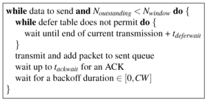 Figure 6: Pseudocode for sending a packet.
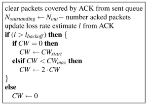 Figure 7: Pseudocode for processing ACKs.
3.5 Handling Multiple Bit-rates
So far in our discussion, we have assumed that all transmissions are
performed at a common bit-rate and power level. To handle
heterogeneous bit-rates, nodes annotate the interferer lists and
defer tables with the bit-rates of the sources when the interference
occurred. The decision to transmit at a node will then depend on the
defer table entry corresponding to the bit-rate of its intended
transmission and of the ongoing transmission. The extensions to
handle multiple power levels are similar. We have not yet incorporated
these bit-rate extensions in our implementation.
In fact, online bit-rate adaptation algorithms can benefit from using the
information in the conflict map in choosing the best rate at which to
transmit. For example, a node may choose to transmit at a lower rate
that can tolerate interference from an ongoing transmission or defer
to the ongoing transmission and transmit at a higher rate later on,
picking the choice that yields a higher throughput. A preliminary evaluation
of CMAP at higher bit-rates (§5.8) indicates
that such an algorithm would amplify CMAP 's gains.
3.6 Beyond Unicast Transmissions
Thus far, we have assumed that all transmissions are unicast. However,
senders may also transmit broadcast packets that are intended to reach
some or all of the node's one-hop neighbors. To make channel access
decisions, such broadcast transmissions could simply be treated as a
collection of unicast transmissions. For example, suppose a node u
wishes to make a broadcast to a set of nodes V. To make a
decision on whether to transmit or not, u uses the transmission
decision process in §3.2 to check that, ∀v ∈ V and for every ongoing transmission p → q, u→ v does not conflict with p → q. In
opportunistic routing [2] however, senders leverage broadcast
transmissions in a slightly different way-the sender broadcasts a
batch of packets to a set of possible "forwarders" that
opportunistically receive and forward some fraction of the packets
each to the destination. In such broadcasts, it is sufficient to
ensure that a packet is correctly received at one of the forwarders,
not all. To handle such broadcasts, the conflict map data structure
described in this section must be augmented with packet reception
rates at receivers in the presence of interference. The sender's
decision on whether to transmit or not will then be based on the
probability that at least one forwarder receives the packet, given the
ongoing transmissions. Adapting CMAP to handle opportunistic routing
is future work.
4 Implementation
In this section, we describe our implementation of CMAP (summarized
in Figure 8) and quantify its overheads. We have
implemented CMAP using the Click [9] router kernel module on
Linux, and commodity 802.11 hardware driven by
MadWifi [10]. To control channel access and retransmissions
from the CMAP kernel module, we disabled carrier sense, link-layer ACKs,
retransmissions and 802.11 backoff in the wireless card. All the nodes
run in the promiscuous ("monitor") mode of the MadWifi driver.
 Figure 8: Architecture of the CMAP prototype; the components shown in
solid lines were implemented by us.
Figure 8: Architecture of the CMAP prototype; the components shown in
solid lines were implemented by us.
4.1 Adaptations For a Software MAC
We now describe the challenges in deploying and evaluating CMAP on
commodity wireless hardware, and the adaptations in our implementation
to overcome these challenges. First, the current 802.11 physical layer
delivers headers of a packet along with the complete packet only after
packet reception has completed, and headers and trailers from a
corrupted packet cannot be recovered. In order to provide a streaming
physical layer abstraction (§2.1) to the link-layer, our
implementation uses a "shim" layer that transmits separate
"header" and "trailer" packets immediately before and after a data
transmission respectively. We will refer to the header, data, and
trailer packets together as a "virtual packet". The shim is
implemented in Click and is located between the link and physical layers.
Second, the gap between the end of a data transmission and arrival of
the corresponding ACK is high in our implementation due to the
communication latency between the software MAC and the hardware
physical layers at both the sender and receiver. For example, in a
typical experiment, this gap was observed to be between 0.5 and 2
milliseconds for about 90% of the data packets, and between 2 and 5
milliseconds for the rest. This latency is excessive because it takes
only about 2 ms to transmit a 1400-byte packet at the lowest data rate
of 6 Mbits/s in 802.11a. This latency also applies to received headers
and trailers, and may prevent senders from processing the received
headers of conflicting transmissions before transmitting data.
To overcome these limitations, our implementation sends
Nvpkt data packets destined to the same node between a
header and trailer in one virtual packet, as shown in
Figure 9. This approach effectively amortizes
the cost of waiting for an ACK over multiple data packets, and allows
senders to react in a timely manner to concurrent transmissions. In
this implementation, defer and backoff decisions are made once per
virtual packet; once a decision to transmit a virtual packet is made,
the header, trailer and all the data packets are sent without any gap
in between. The receiver sends an ACK after receiving the trailer of a
virtual packet; the bitmap contained in the ACK acknowledges the
receipt of individual data packets within a virtual packet.
 Figure 9: Virtual packet format in the CMAP prototype.
4.2 Choosing Values For Design Parameters
We now discuss the implementation choices for the various design
parameters of CMAP . Our implementation uses tdeferwait = tackwait = 5 ms to accommodate the propagation delay
between the link and physical layers, as measured in
§4.1. We use Nvpkt = 32 in our
implementation because such a CMAP implementation has comparable
performance to the commodity 802.11 protocol-the single link
throughput of CMAP at 6 Mbits/s is 5.04 Mbits/s while that of 802.11 with
link-layer ACKs is 5.07 Mbits/s-enabling a fair comparison of CMAP
and 802.11. The send window of unacknowledged packets is set to
Nwindow = 8 virtual packets, or 256 data packets. The
contention window parameters CWstart and
CWmax are set to the corresponding 802.11 values scaled
by Nvpkt-5 ms and 320 ms respectively.
5 Evaluation
The goal of this section is to measure CMAP 's ability to improve
wireless network throughput by increasing the amount of spatial reuse.
To this end, we compare the performance of our CMAP software
prototype (described in §4) to that of the 802.11 MAC with
carrier sense enabled (the "status quo"), and 802.11 with carrier
sense disabled. We summarize our results below.
- In experiments with two pairs of senders and receivers, CMAP
successfully exploits concurrent transmission opportunities to achieve
up to 2× improvement over 802.11 with carrier
sense when the nodes are in an exposed terminal
situation (§5.2), while effectively avoiding
interfering concurrent transmissions using the conflict map data
structure (§5.3). CMAP 's windowed retransmission
protocol is central to realizing the full throughput gain in exposed
terminal cases.
- The impact of "hidden interferers" that are out of
communication range of either the sender or receiver on CMAP
throughput is small (§5.4), and CMAP 's backoff
scheme ensures no performance degradation compared to the status quo
in such cases (§5.5).
- In realistic access point-based topologies with multiple
concurrent senders, CMAP improves aggregate throughput by between
21% and 47%
and median per-source throughput by 1.8× compared to the
status quo by exploiting exposed terminal
opportunities (§5.6).
- CMAP improves throughput by 52% compared to the status quo in
two-hop content dissemination mesh topologies (§5.7).
- CMAP 's performance benefits apply across multiple
bit-rates (§5.8).
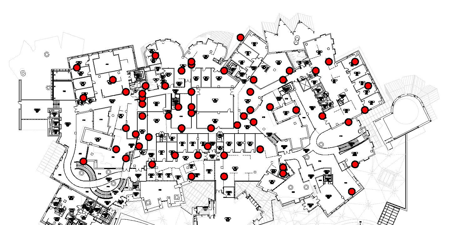 Figure 10: A map of our 50-node indoor wireless testbed.
5.1 Experimental Testbed and Method
Our testbed consists of Soekris net4526 computers with a 133 MHz 486
processor running the 2.4.26 Linux kernel. The nodes are equipped with
an 802.11 a/b/g mini-PCI card based on the Atheros AR5212 chipset.
The testbed nodes are located in one large floor of an office building
as shown in Figure 10. Transmitting in isolation, of
the 2162 node pairs that have any connectivity whatsoever,
approximately 68% links have a packet reception rate (PRR) less than
0.1, 12% have a PRR greater than 0.1 and less than 1, and 20% have a
PRR of 1. Considering just the latter two types of links, the nodes
in our testbed have a mean degree of 15.2 and a median degree of
17.
We perform all our experiments in the 5 GHz 802.11a band which had
negligible background traffic; we leave an evaluation of CMAP in
other frequency bands with different propagation characteristics and
potentially more non-CMAP background traffic to future work.
Unless mentioned otherwise, all
senders transmit 1400-byte data packets at the 6 Mbits/s bit-rate of
802.11a as fast as they can. Each run of an experiment lasts for
100 seconds and the aggregate throughput achieved is measured as the
total number of non-duplicate data packets received per second at the
designated receivers, computed over the last 60 seconds of the
experiment.
We pick sender-receiver pairs in each experiment based on measurements
of PRR and average signal strength between pairs of nodes at 6 Mbits/s
and in the absence of any other concurrent transmission, obtained
shortly before running the corresponding experiment. In all
experiments below, we define two nodes a and b to be "in-range"
of each other if both the links a → b and b →a have a PRR above 0.2 and signal strength above the 10th percentile
of the signal strength of all links network-wide. We call a link a→ b a "potential transmission link" if both the links a→ b and b → a have a PRR above 0.9 and signal
strength above the 10th percentile of the signal strength of all links
network-wide; we pick only such links to send data in our experiments
because any routing protocol running on this testbed typically
selects such links. Note that while the PRR of a link alone could
serve as a good metric to decide whether the link is a potential
transmission link or not, we also use a low signal strength threshold
to eliminate very weak links whose performance would degrade
precipitously in the presence of other transmissions in the network.
 Figure 11: Constraints on topologies in experiments with exposed
terminals (§5.2), two senders
in-range (§5.3) and
out of range (§5.5), and mesh
topologies (§5.7). All links that are not annotated in
the figure are unconstrained.
Figure 11: Constraints on topologies in experiments with exposed
terminals (§5.2), two senders
in-range (§5.3) and
out of range (§5.5), and mesh
topologies (§5.7). All links that are not annotated in
the figure are unconstrained.
5.2 CMAP Exploits Exposed Terminals
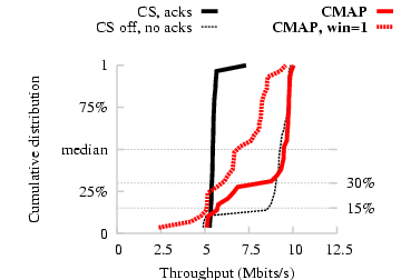 Figure 12: Experiment with exposed terminals. CMAP achieves a 2×
gain over 802.11 with carrier sense.
In this experiment we seek to quantify the maximum throughput gain two
simultaneous wireless data streams can achieve in an exposed terminal
configuration. Since this situation occurs frequently in busy access
point-based wireless networks [6], we expect the gains
we find in the results to be applicable to such networks.
We pick pairs of links from our 50-node testbed, as shown in
Figure 11(a), such that: (i) the two senders are
in range of each other, (ii) each sender-receiver pair is a potential
transmission link (as per the definitions in §5.1),
(iii) the signal strength from a sender to its corresponding receiver
is strong (in the 90th percentile of signal strength of all links
network-wide), and (iv) the signal strength between all other pairs of
nodes is somewhat weak (below the 90th percentile threshold). The last
two constraints ensure that the two transmissions do not interfere very
much, most likely resulting in an exposed terminal situation.
Figure 12 presents the distribution of
throughput across 50 exposed terminal configurations chosen at
random from all possible configurations. With carrier sense enabled,
we see that most link pairs achieve little more than the
single-link rate of 5 Mbits/s, since most of the time, each sender
defers its transmission to the other.
With carrier sense and link-layer ACKs disabled (thin dashed curve),
we see that 15% of the pairs are not in fact exposed terminals in the
sense that the two transmissions do not simultaneously achieve their
maximum throughput. Of the remaining 85% of pairs in this
experiment, CMAP permits the two transmissions to proceed concurrently
[70%/85%]=82% of the time, resulting in a throughput
improvement of approximately 2× over 802.11 with carrier sense
enabled. By carefully scrutinizing the experiment logs, we verified that
the remaining 18% of pairs experienced many spurious
retransmissions due to very high ACK loss rates
that our windowed ACK scheme could not completely
eliminate.
To quantify the benefits of our windowed retransmission
protocol, we repeated the CMAP experiments with a window size of one
virtual packet. We found that the median throughput improvement in
this case was just 1.5×, significantly lower than CMAP
with a window of eight virtual packets, because ACKs collided
frequently at the senders and caused the senders to timeout and
perform spurious retransmissions.
Figure 12: Experiment with exposed terminals. CMAP achieves a 2×
gain over 802.11 with carrier sense.
In this experiment we seek to quantify the maximum throughput gain two
simultaneous wireless data streams can achieve in an exposed terminal
configuration. Since this situation occurs frequently in busy access
point-based wireless networks [6], we expect the gains
we find in the results to be applicable to such networks.
We pick pairs of links from our 50-node testbed, as shown in
Figure 11(a), such that: (i) the two senders are
in range of each other, (ii) each sender-receiver pair is a potential
transmission link (as per the definitions in §5.1),
(iii) the signal strength from a sender to its corresponding receiver
is strong (in the 90th percentile of signal strength of all links
network-wide), and (iv) the signal strength between all other pairs of
nodes is somewhat weak (below the 90th percentile threshold). The last
two constraints ensure that the two transmissions do not interfere very
much, most likely resulting in an exposed terminal situation.
Figure 12 presents the distribution of
throughput across 50 exposed terminal configurations chosen at
random from all possible configurations. With carrier sense enabled,
we see that most link pairs achieve little more than the
single-link rate of 5 Mbits/s, since most of the time, each sender
defers its transmission to the other.
With carrier sense and link-layer ACKs disabled (thin dashed curve),
we see that 15% of the pairs are not in fact exposed terminals in the
sense that the two transmissions do not simultaneously achieve their
maximum throughput. Of the remaining 85% of pairs in this
experiment, CMAP permits the two transmissions to proceed concurrently
[70%/85%]=82% of the time, resulting in a throughput
improvement of approximately 2× over 802.11 with carrier sense
enabled. By carefully scrutinizing the experiment logs, we verified that
the remaining 18% of pairs experienced many spurious
retransmissions due to very high ACK loss rates
that our windowed ACK scheme could not completely
eliminate.
To quantify the benefits of our windowed retransmission
protocol, we repeated the CMAP experiments with a window size of one
virtual packet. We found that the median throughput improvement in
this case was just 1.5×, significantly lower than CMAP
with a window of eight virtual packets, because ACKs collided
frequently at the senders and caused the senders to timeout and
perform spurious retransmissions.
5.3 CMAP Avoids Interfering Transmissions
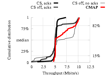 Figure 13: Experiment with two senders in range of each other. CMAP
correctly identifies interfering concurrent transmissions.
We now evaluate CMAP on more general two-sender topologies. In this
experiment, we evaluate the performance of CMAP on a topology with two
sender-receiver pairs such that the two senders are in hearing range
of each other. This experiment tests whether the defer scheme
correctly discriminates between interfering and non-interfering
concurrent transmissions.
We choose two sender-receiver pairs for this experiment as shown in
Figure 11(b): the two senders are in range of each
other, and each sender-receiver pair is a potential transmission link;
unlike in the experiments with exposed
terminals (§5.2), we impose no additional
constraints on the signal strengths of the links. Note that some pairs
of links could well be exposed terminals.
Figure 13 presents the distribution of
throughput across 50 link pairs chosen at random. On 15% of the link
pairs, simultaneous transfers were deleterious, evidenced by the worse
performance of 802.11 with carrier sense disabled compared to 802.11
with carrier sense enabled. For these link pairs, CMAP correctly directs that
each transmission defer to the other and tracks the performance of
802.11 with carrier sense on (5 Mbits/s). However, there are link
pairs in this experiment that are better off transmitting concurrently
(18% of them on the right-hand side of the CDF), for which 802.11
with carrier sense and link-layer ACKs disabled offers a throughput
improvement up to 2×. For these link pairs, CMAP correctly directs
transmissions to occur simultaneously, and thus achieves roughly the
same throughput improvements as 802.11 with carrier sense
disabled. Also note that, over link pairs that are on the right side
of the CDF, 802.11 with carrier sense disabled performs worse than CMAP
when link-layer ACKs were enabled because 802.11 uses a stop-and-wait
transmission method (unlike CMAP 's windowed retransmission scheme)
and hence is more vulnerable to the ACK loss problem.
Figure 13: Experiment with two senders in range of each other. CMAP
correctly identifies interfering concurrent transmissions.
We now evaluate CMAP on more general two-sender topologies. In this
experiment, we evaluate the performance of CMAP on a topology with two
sender-receiver pairs such that the two senders are in hearing range
of each other. This experiment tests whether the defer scheme
correctly discriminates between interfering and non-interfering
concurrent transmissions.
We choose two sender-receiver pairs for this experiment as shown in
Figure 11(b): the two senders are in range of each
other, and each sender-receiver pair is a potential transmission link;
unlike in the experiments with exposed
terminals (§5.2), we impose no additional
constraints on the signal strengths of the links. Note that some pairs
of links could well be exposed terminals.
Figure 13 presents the distribution of
throughput across 50 link pairs chosen at random. On 15% of the link
pairs, simultaneous transfers were deleterious, evidenced by the worse
performance of 802.11 with carrier sense disabled compared to 802.11
with carrier sense enabled. For these link pairs, CMAP correctly directs that
each transmission defer to the other and tracks the performance of
802.11 with carrier sense on (5 Mbits/s). However, there are link
pairs in this experiment that are better off transmitting concurrently
(18% of them on the right-hand side of the CDF), for which 802.11
with carrier sense and link-layer ACKs disabled offers a throughput
improvement up to 2×. For these link pairs, CMAP correctly directs
transmissions to occur simultaneously, and thus achieves roughly the
same throughput improvements as 802.11 with carrier sense
disabled. Also note that, over link pairs that are on the right side
of the CDF, 802.11 with carrier sense disabled performs worse than CMAP
when link-layer ACKs were enabled because 802.11 uses a stop-and-wait
transmission method (unlike CMAP 's windowed retransmission scheme)
and hence is more vulnerable to the ACK loss problem.
5.4 How Bad Are Hidden Interferers?
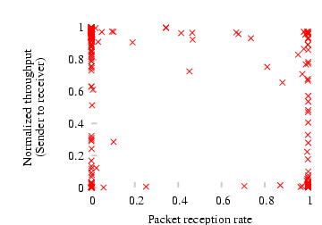 Figure 14: Scatter plot of the normalized throughput of a pair S → R in the presence of an interferer I vs. the minimum
of the packet reception rates of the links I → R and I → S.
CMAP 's conflict map and defer mechanisms can fail to detect
conflicting transmissions when either (a) the receiver is unable to
receive at least some headers and trailers from an interferer
in order to populate its interferer list, and thereby the conflict
map, or (b) a potential sender cannot hear the interferer's
transmission headers in order to defer to it (the hidden terminals
problem). As a result, an interferer that is out of communication
range of either the receiver or the sender of a transmission (a
"hidden interferer") can degrade the throughput of that
transmission. In this section, we evaluate the frequency of hidden
interferers and their impact on CMAP throughput.
To identify the frequency of hidden interferers, we quantify the
relationship between an interferer I's effect on the throughput of a
transmission S → R and the probability that S and R
can hear I. In this experiment, we randomly choose 500 pairs of
sender-receiver pairs (S, R) with a potential transmission link
between them, and for each pair, we pick an interferer I at random
from all the nodes in the testbed. We first measure the throughput of
the link S → R and the PRRs of the links I → R
and I → S in the absence of any other interference. S
and I then transmit 802.11 packets continuously and simultaneously
with carrier sense and link-layer ACKs disabled3, and we measure the throughput of S → R in the
presence of I's transmissions.
Figure 14 shows a scatter plot of the normalized
throughput of S → R with interference (the ratio of the
throughput of S → R in the presence of I's interference
to that in the absence of interference) on the Y-axis, and the minimum
of the packet reception rates of I → R and I →S on the X-axis. Note that the data points that lie near the left
bottom of this graph correspond to hidden interferers, because for
such points I reduces the throughput of S → R and yet is
out of communication range of either S or R. From the data, we
find that the fraction of points that lie in the left bottom quadrant of
the plot (i.e., the fraction of cases where I reduces the throughput
of S → R by more than 50%, but has a link with PRR less
than 0.5 to either S or R) is only 8%. This observation convinces
us that hidden interferers do not occur very frequently in our
experiments.
We now estimate the magnitude of impact a hidden interferer has on
CMAP throughput as follows. Let pr and ps denote the packet
reception rates of the links I → R and I → S
respectively. Then the probability that both S and R hear I is
at least p = max(pr + ps −1, 0). Let T denote the normalized
throughput of S → R in the presence of I. Now, had the
experiment been run with CMAP , the conflict detection mechanism would
have avoided a throughput degradation (i.e., resulted in a normalized
throughput of 1) with a probability p, and resulted in a lower
throughput of T with a probability 1−p. Hence, the expected
throughput of S → R with CMAP can be computed as p·1 + (1−p)·T. A sum of the above expression over all data
points in Figure 14 works out to be 0.896. Thus,
the expected damage to a CMAP pair's throughput due to a hidden
interferer is only around 10%. In practice, however, the degradation
will be even smaller (as we will see next) because CMAP senders
back off in response to losses, unlike the senders in the above
experiment which were made to transmit continuously.
Figure 14: Scatter plot of the normalized throughput of a pair S → R in the presence of an interferer I vs. the minimum
of the packet reception rates of the links I → R and I → S.
CMAP 's conflict map and defer mechanisms can fail to detect
conflicting transmissions when either (a) the receiver is unable to
receive at least some headers and trailers from an interferer
in order to populate its interferer list, and thereby the conflict
map, or (b) a potential sender cannot hear the interferer's
transmission headers in order to defer to it (the hidden terminals
problem). As a result, an interferer that is out of communication
range of either the receiver or the sender of a transmission (a
"hidden interferer") can degrade the throughput of that
transmission. In this section, we evaluate the frequency of hidden
interferers and their impact on CMAP throughput.
To identify the frequency of hidden interferers, we quantify the
relationship between an interferer I's effect on the throughput of a
transmission S → R and the probability that S and R
can hear I. In this experiment, we randomly choose 500 pairs of
sender-receiver pairs (S, R) with a potential transmission link
between them, and for each pair, we pick an interferer I at random
from all the nodes in the testbed. We first measure the throughput of
the link S → R and the PRRs of the links I → R
and I → S in the absence of any other interference. S
and I then transmit 802.11 packets continuously and simultaneously
with carrier sense and link-layer ACKs disabled3, and we measure the throughput of S → R in the
presence of I's transmissions.
Figure 14 shows a scatter plot of the normalized
throughput of S → R with interference (the ratio of the
throughput of S → R in the presence of I's interference
to that in the absence of interference) on the Y-axis, and the minimum
of the packet reception rates of I → R and I →S on the X-axis. Note that the data points that lie near the left
bottom of this graph correspond to hidden interferers, because for
such points I reduces the throughput of S → R and yet is
out of communication range of either S or R. From the data, we
find that the fraction of points that lie in the left bottom quadrant of
the plot (i.e., the fraction of cases where I reduces the throughput
of S → R by more than 50%, but has a link with PRR less
than 0.5 to either S or R) is only 8%. This observation convinces
us that hidden interferers do not occur very frequently in our
experiments.
We now estimate the magnitude of impact a hidden interferer has on
CMAP throughput as follows. Let pr and ps denote the packet
reception rates of the links I → R and I → S
respectively. Then the probability that both S and R hear I is
at least p = max(pr + ps −1, 0). Let T denote the normalized
throughput of S → R in the presence of I. Now, had the
experiment been run with CMAP , the conflict detection mechanism would
have avoided a throughput degradation (i.e., resulted in a normalized
throughput of 1) with a probability p, and resulted in a lower
throughput of T with a probability 1−p. Hence, the expected
throughput of S → R with CMAP can be computed as p·1 + (1−p)·T. A sum of the above expression over all data
points in Figure 14 works out to be 0.896. Thus,
the expected damage to a CMAP pair's throughput due to a hidden
interferer is only around 10%. In practice, however, the degradation
will be even smaller (as we will see next) because CMAP senders
back off in response to losses, unlike the senders in the above
experiment which were made to transmit continuously.
5.5 CMAP Handles Hidden Terminals Well
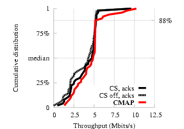 Figure 15: Experiment with two senders out of each other's transmission
range. CMAP 's backoff strategy avoids performance degradation
compared to status quo.
We now evaluate how well CMAP 's backoff protocol prevents performance
degradation when the defer mechanism fails in an experiment with pairs
of hidden terminals. We choose pairs of links for this experiment as
shown in Figure 11(c): each receiver has a potential
transmission link to both senders (as per the definitions in
§5.1), ensuring that the two transmissions will
almost always interfere with each other at the receivers. The senders
are not in range of each other with the result that they cannot defer
to each other's transmissions.
Figure 15 presents the distribution of
throughput across 50 randomly chosen link pairs. We see that CMAP and
802.11 (with both carrier sense enabled and disabled) perform
comparably. Also note that there is very little weight on the
right-hand side of the CDF that represents throughputs greater than
the single pair throughput. This is because the best we can hope for
in such topologies, with current 802.11 hardware, is transmissions
interleaved with each other to achieve the throughput of a
single sender-receiver pair.
Figure 15: Experiment with two senders out of each other's transmission
range. CMAP 's backoff strategy avoids performance degradation
compared to status quo.
We now evaluate how well CMAP 's backoff protocol prevents performance
degradation when the defer mechanism fails in an experiment with pairs
of hidden terminals. We choose pairs of links for this experiment as
shown in Figure 11(c): each receiver has a potential
transmission link to both senders (as per the definitions in
§5.1), ensuring that the two transmissions will
almost always interfere with each other at the receivers. The senders
are not in range of each other with the result that they cannot defer
to each other's transmissions.
Figure 15 presents the distribution of
throughput across 50 randomly chosen link pairs. We see that CMAP and
802.11 (with both carrier sense enabled and disabled) perform
comparably. Also note that there is very little weight on the
right-hand side of the CDF that represents throughputs greater than
the single pair throughput. This is because the best we can hope for
in such topologies, with current 802.11 hardware, is transmissions
interleaved with each other to achieve the throughput of a
single sender-receiver pair.
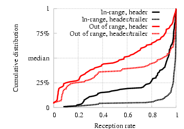 Figure 16: Probabilities of reception of either header or trailer and
header alone for each transmitted virtual packet, computed from the
experiments with two pairs of senders in-range (§5.3)
and out of range (§5.5).
We also use the above experiment to validate our design decision of
transmitting both headers and trailers (as opposed to only headers) on
packets. For each experiment with two senders in
§5.3 and §5.5, we compute the
fraction of virtual packets transmitted by a sender for which either
the header or the trailer was successfully received by the
receiver. We compare this fraction against the fraction of virtual
packets for which the header was received. We plot a CDF of these
fractions across all sender-receiver pairs in each experiment in
Figure 16. We see that the probability of
reception of a header or trailer is higher than the probability of
reception of a header alone in both the experiments; the benefit of using
trailers is more pronounced when the senders were out of
each other's range and persistently collided at the receivers. We also
observe that the probability that either a header or trailer is
received is almost 1 in the experiment where the senders are in range
of each other and transmit equal-sized packets.
Figure 16: Probabilities of reception of either header or trailer and
header alone for each transmitted virtual packet, computed from the
experiments with two pairs of senders in-range (§5.3)
and out of range (§5.5).
We also use the above experiment to validate our design decision of
transmitting both headers and trailers (as opposed to only headers) on
packets. For each experiment with two senders in
§5.3 and §5.5, we compute the
fraction of virtual packets transmitted by a sender for which either
the header or the trailer was successfully received by the
receiver. We compare this fraction against the fraction of virtual
packets for which the header was received. We plot a CDF of these
fractions across all sender-receiver pairs in each experiment in
Figure 16. We see that the probability of
reception of a header or trailer is higher than the probability of
reception of a header alone in both the experiments; the benefit of using
trailers is more pronounced when the senders were out of
each other's range and persistently collided at the receivers. We also
observe that the probability that either a header or trailer is
received is almost 1 in the experiment where the senders are in range
of each other and transmit equal-sized packets.
5.6 Access Point Topology
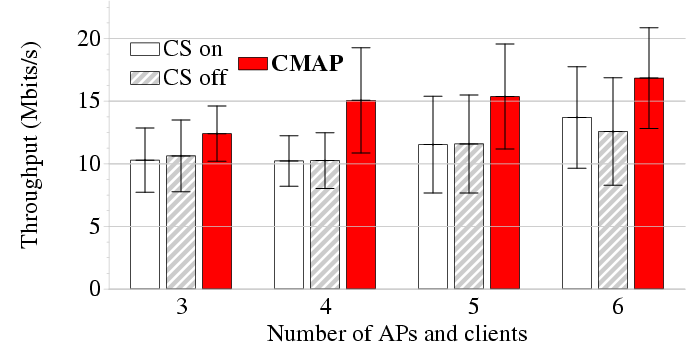 Figure 17: Mean throughput in the experiment with N APs and N
clients; error bars show standard deviation. CMAP
achieves between 21% and 47% more throughput than the status quo.
In this section, we evaluate CMAP on larger topologies with multiple
concurrent senders. We pick topologies that resemble wireless local
area networks (WLANs) with multiple access points (APs) and
clients that span a geographical area several radio-ranges in
diameter.
We divide the testbed (see Figure 10) into six
"regions" and designate one node in each region as an AP, such that
each AP is out of the communication range of every other AP. We choose
clients of an AP from the set of nodes in that region that have a
potential transmission link to that AP, and randomly designate one of
the client or AP as the sender of packets. We then perform experiments
by varying the number of APs (N) from three through six, always
choosing APs from adjacent regions when there are fewer than six APs
in an experiment.
For each value of N, we perform 10 experiments with different clients for APs each time.
Figure 17: Mean throughput in the experiment with N APs and N
clients; error bars show standard deviation. CMAP
achieves between 21% and 47% more throughput than the status quo.
In this section, we evaluate CMAP on larger topologies with multiple
concurrent senders. We pick topologies that resemble wireless local
area networks (WLANs) with multiple access points (APs) and
clients that span a geographical area several radio-ranges in
diameter.
We divide the testbed (see Figure 10) into six
"regions" and designate one node in each region as an AP, such that
each AP is out of the communication range of every other AP. We choose
clients of an AP from the set of nodes in that region that have a
potential transmission link to that AP, and randomly designate one of
the client or AP as the sender of packets. We then perform experiments
by varying the number of APs (N) from three through six, always
choosing APs from adjacent regions when there are fewer than six APs
in an experiment.
For each value of N, we perform 10 experiments with different clients for APs each time.
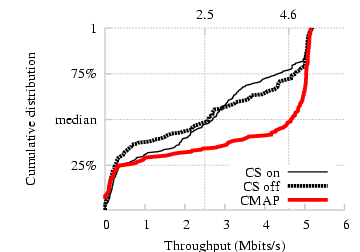 Figure 18: CDF of the per-sender throughput in experiments with N APs
and N clients. CMAP increases the median by
a factor of 1.8.
Figure 17 shows the average aggregate throughput of
CMAP and 802.11 (with both carrier sense enabled and disabled) as a
function of the number of concurrent senders N in the experiment. We
find that CMAP improves aggregate throughput by between 21% (when
N = 3) and 47% (when N = 4). CMAP sees this improvement because
pairs of senders in adjacent cells were often exposed
terminals. Figure 18 shows a CDF of the per-sender
throughput for all senders across all experiments. From the figure we
find that CMAP improves the median per-sender throughput by a factor
of 1.8 compared to 802.11.
We next study how the header or trailer reception probabilities at a
node are affected by the number of concurrent transmissions in the
network. Figure 19 shows the mean, median, and
various percentile values of the probability of reception of either a
header or trailer of a virtual packet at each receiver, as a function
of the number of concurrent transmissions in the network. We find from
the graph that the median header or trailer reception probability is
practically unaffected by the number of concurrent
transmissions. However, the 10th percentile value drops sharply,
indicating that a small fraction of receivers cannot implement the
conflict map mechanisms effectively in the presence of many concurrent
transmissions. To increase the robustness of CMAP to header or
trailer loss in such cases, we can replicate the header and trailer
information (an overhead of 24 bytes) in every data packet of a
virtual packet.
Figure 18: CDF of the per-sender throughput in experiments with N APs
and N clients. CMAP increases the median by
a factor of 1.8.
Figure 17 shows the average aggregate throughput of
CMAP and 802.11 (with both carrier sense enabled and disabled) as a
function of the number of concurrent senders N in the experiment. We
find that CMAP improves aggregate throughput by between 21% (when
N = 3) and 47% (when N = 4). CMAP sees this improvement because
pairs of senders in adjacent cells were often exposed
terminals. Figure 18 shows a CDF of the per-sender
throughput for all senders across all experiments. From the figure we
find that CMAP improves the median per-sender throughput by a factor
of 1.8 compared to 802.11.
We next study how the header or trailer reception probabilities at a
node are affected by the number of concurrent transmissions in the
network. Figure 19 shows the mean, median, and
various percentile values of the probability of reception of either a
header or trailer of a virtual packet at each receiver, as a function
of the number of concurrent transmissions in the network. We find from
the graph that the median header or trailer reception probability is
practically unaffected by the number of concurrent
transmissions. However, the 10th percentile value drops sharply,
indicating that a small fraction of receivers cannot implement the
conflict map mechanisms effectively in the presence of many concurrent
transmissions. To increase the robustness of CMAP to header or
trailer loss in such cases, we can replicate the header and trailer
information (an overhead of 24 bytes) in every data packet of a
virtual packet.
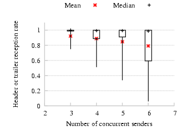 Figure 19: Mean and median probabilities of reception of either header
or trailer of a virtual packet at a receiver, as a function of the
number of concurrent senders in the experiment. The thick error bars
represent the 25th and 75th percentiles, and the thin error bars
show the 10th and 90th percentile values.
Figure 19: Mean and median probabilities of reception of either header
or trailer of a virtual packet at a receiver, as a function of the
number of concurrent senders in the experiment. The thick error bars
represent the 25th and 75th percentiles, and the thin error bars
show the 10th and 90th percentile values.
5.7 Mesh Topology
In this section, we present an evaluation of CMAP over a
two-hop content dissemination mesh network shown in
Figure 11(d). The source S first broadcasts a batch
of packets to its one-hop neighbors A1, A2, and A3. The
Ais then transmit the packets to the corresponding Bis. We
compute the throughput at each Bi as the minimum of the throughputs
along the corresponding S → Ai and Ai → Bi
paths. We measured the aggregate throughput at all the Bis over 10
different topologies. We found that CMAP achieves a 52% higher
average throughput than 802.11 with carrier sense enabled. The reason
for this improvement was that, frequently, one or more of the Ais were
exposed terminals during the Ai → Bi transfers.
While the above experiment may not be representative of the
performance of CMAP over arbitrary mesh networks, it convinces us
that multi-hop mesh networks can benefit from a MAC that exploits
concurrent transmission opportunities. In fact, given a MAC like CMAP
that increases concurrency, routing protocol design should be rethought
to generate topologies that increase concurrent transmission
opportunities.
5.8 Variable Bit-rates
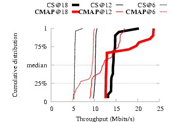 Figure 20: Experiment with exposed terminals transmitting at 6,
12 and 18 Mbits/s rates of 802.11a. CMAP continues to exploit
exposed terminal opportunities at higher bit-rates.
Thus far all experiments have reported performance figures from the
802.11a 6 Mbits/s bit-rate. In practice, however, wireless senders
may run at many of the higher bit-rates available to increase
throughput. Consequently, we seek to measure if CMAP can continue to
exploit exposed terminal opportunities at higher bit-rates.
We repeat the experiment with exposed terminals, as in
§5.2, at the 12 and 18 Mbits/s rates of 802.11a. In
each experiment, all the senders run at a common bit-rate that we set
manually, and do not perform any online rate adaptation. Also, CMAP
nodes were always made to transmit interferer list updates, headers,
trailers and ACK packets at the lowest bit-rate irrespective of the
bit-rate of data packets, resulting in a slight performance penalty at
higher bit-rates. The CDFs of the throughputs of CMAP and 802.11
with carrier sense enabled at bit-rates of 6, 12 and 18 Mbits/s are
shown in Figure 20. We see from the figure that CMAP
continues to show throughput improvements over 802.11 at higher
bit-rates. Note however that the number of exposed terminal
opportunities decreases with increasing bit-rates because the minimum
SINR required to decode an incoming packet increases with increasing
bit-rates; as a result, some pairs of links that could transmit
concurrently at lower rates cannot do so at higher rates.
Figure 20: Experiment with exposed terminals transmitting at 6,
12 and 18 Mbits/s rates of 802.11a. CMAP continues to exploit
exposed terminal opportunities at higher bit-rates.
Thus far all experiments have reported performance figures from the
802.11a 6 Mbits/s bit-rate. In practice, however, wireless senders
may run at many of the higher bit-rates available to increase
throughput. Consequently, we seek to measure if CMAP can continue to
exploit exposed terminal opportunities at higher bit-rates.
We repeat the experiment with exposed terminals, as in
§5.2, at the 12 and 18 Mbits/s rates of 802.11a. In
each experiment, all the senders run at a common bit-rate that we set
manually, and do not perform any online rate adaptation. Also, CMAP
nodes were always made to transmit interferer list updates, headers,
trailers and ACK packets at the lowest bit-rate irrespective of the
bit-rate of data packets, resulting in a slight performance penalty at
higher bit-rates. The CDFs of the throughputs of CMAP and 802.11
with carrier sense enabled at bit-rates of 6, 12 and 18 Mbits/s are
shown in Figure 20. We see from the figure that CMAP
continues to show throughput improvements over 802.11 at higher
bit-rates. Note however that the number of exposed terminal
opportunities decreases with increasing bit-rates because the minimum
SINR required to decode an incoming packet increases with increasing
bit-rates; as a result, some pairs of links that could transmit
concurrently at lower rates cannot do so at higher rates.
6 Related Work
Spatial reuse is a well-known concept in wireless communications
networks of many different types. MACA [7] makes
the observation that carrier sense cannot make correct transmission
decisions because it does not consider channel conditions at the
receiver, resulting in problems like exposed and hidden terminals. The
paper proposes the RTS/CTS virtual carrier sensing protocol to solve
the hidden terminal problem. However, this mechanism does not solve
the exposed terminal problem.
In a busy access point WiFi network, Judd [6] observes
that many clients connected to different access points are in fact
exposed terminals with respect to each other. In fact, two
randomly-chosen clients are as likely to be exposed terminals
with respect to each other as they are to connect to the same access
point. This result suggests that the use of conflict maps could
significantly improve performance in infrastructure wireless LANs.
There have been a few previous proposals to increase concurrency in
wireless networks [1,11,16,3]. As we explain below, however, CMAP
differs from all these schemes in the method of identifying and
exploiting the identified concurrent transmission opportunities. Also, these
previous proposals build upon the RTS/CTS mechanism and evaluate their
ideas in simulation alone.
Like CMAP , the "adaptive learning" extension of
MACA-P [1] builds a data structure containing
potentially non-interfering but nearby nodes. Unlike CMAP however,
MACA-P is based on the RTS/CTS exchange, extended in time to include a
control gap, which results in a significant protocol overhead.
RTSS/CTSS [11] uses an offline training phase to
determine which nodes may transmit concurrently. This approach,
however, is not applicable when the channel varies, as is the case in
practice. It also does not have any mechanisms to deal
with the ACK loss problem in exposed terminals.
Shukla et al. [16] propose identifying exposed
terminals performing an RTS/CTS exchange on the basis of overhearing
an RTS without overhearing a CTS. This method does not
identify all exposed terminal opportunities-it misses exposed
terminals where a sender can hear another receiver's CTS,
but is far enough from the receiver that it can transmit concurrently.
In the Interference Aware (IA) MAC protocol [3], nodes
make transmission decisions using the SINR estimates at
receivers that are embedded in CTS messages. However, the IA MAC
misses exposed terminals where one of the exposed senders does not
hear the CTS from the other receiver.
There have also been proposals to use receiver-based feedback of
channel conditions in making transmission decisions to improve the
performance of CSMA. E-CSMA [4] uses observed
channel conditions at the transmitter (RSSI, for example), and
receiver-based packet success feedback to build a per-receiver
probability distribution of transmission success conditioned on the
channel conditions at the sender at the time of transmission. Then a
node makes a transmit/defer decision based on transmitter channel
conditions just before sending a packet. The distinguishing feature of
CMAP from E-CSMA is that CMAP explicitly takes the identity of current
senders and whom they're sending to into account while making channel
access decisions, instead of implicitly capturing them using signal
strength estimates, and hence can better predict which transmissions
are likely to succeed and which not.
Other researchers have observed that concurrent transmissions do not
always result in both the colliding packets being
lost [18,20]. This phenomenon, in which
a receiver can correctly decode it's sender's packet even in the
presence of other concurrent transmissions, is sometimes referred to
as the "capture" effect. CMAP increases the opportunities for and
exploits packet capture by increasing the number of concurrent
transmissions. Whitehouse et al. [20] and
Priyantha [15] propose mechanisms to boost the chances
of packet capture. In these schemes, receivers acquire packet
preambles throughout the duration of ongoing packet receptions in
addition to when no packet is being received, thereby capturing
stronger transmissions that start during the reception of weaker
transmissions. These schemes can improve CMAP 's performance by
helping it build up state about the network gleaned from stronger and
later transmissions.
Padhye et al. [14] propose a set of metrics that estimate
link interference in static multi-hop wireless networks. They suggest
an offline process of pairwise link measurements to identify
conflicting transmissions. Similarly, the interference
map [13] builds up packet success information about CSMA
transmissions in an offline training phase, for the purpose of network
planning. CMAP , in contrast, obtains interference information
online.
Algorithms to tune the carrier sense threshold or power level
alone [12,17,19,21,22] and algorithms that tune both carrier
sense threshold and transmit power [8] build on the
basic carrier sense mechanism. Thus, these algorithms make a
fundamental trade-off between preventing hidden-terminal collisions
and permitting exposed-terminal spatial reuse, and don't fully take
advantage of the many exposed terminal opportunities present in real
networks. CMAP explicitly discriminates between conflicting and
non-conflicting transmissions, avoiding this tradeoff.
7 Conclusions
We presented the design, prototype implementation, and experimental
evaluation of CMAP , a reactive channel access protocol that uses
empirical observations of packet loss to build a distributed data
structure of interfering concurrent transmissions (called the
conflict map) in a wireless network. We showed how nodes can use
this conflict map data structure to transmit concurrently with each
other when transmissions do not interfere-almost all exposed
terminal configurations see a 2× gain in our
experiments-while successfully avoiding conflicting concurrent
transmissions, thereby increasing the aggregate throughput of the
system. Though flows under CMAP may experience transient packet loss
before conflict map entries converge, we believe that the gains with
CMAP outweigh this loss, especially in topologies with scope for
spatial reuse.
Our evaluation of CMAP over realistic access point topologies with
multiple concurrent senders shows that CMAP improves aggregate throughput by
up to 47% and median per-sender throughput by 1.8× over
802.11 by exploiting concurrent transmission opportunities.
Acknowledgments
We thank our shepherd Brad Karp and the anonymous reviewers for their
insightful comments. This work was supported in part by the National
Science Foundation under Grants CNS-0721702 and CNS-0520032, and by a
Cisco Fellowship.
References
- [1]
-
A. Acharya, A. Misra, and S. Bansal.
Design and Analysis of a Cooperative Medium Access Scheme for
Wireless Mesh Networks.
In Proc. of IEEE BROADNETS, pages 621-631, San Jose, CA,
Oct. 2004.
- [2]
-
S. Biswas and R. Morris.
Opportunistic Routing in Multi-Hop Wireless Networks.
In Proc. of ACM SIGCOMM, pages 69-74, Philadelphia, PA,
August 2005.
- [3]
-
M. Cesana, D. Maniezzo, P. Bergamo, and M. Gerla.
Interference Aware (IA) MAC: an Enhancement to IEEE 802.11b DCF.
In Proc. of IEEE Vehicular Technology Conf., number 5, pages
2799-2803, Oct. 2003.
- [4]
-
S. Eisenmann and A. Campbell.
E-CSMA: Supporting Enhanced CSMA Performance in Experimental Sensor
Networks using Per-neighbor Transmission Probability Thresholds.
In Proc. of IEEE INFOCOM, pages 1208-1216, Anchorage, AK,
May 2007.
- [5]
-
K. Jamieson and H. Balakrishnan.
PPR: Partial Packet Recovery for Wireless Networks.
In Proc. of ACM SIGCOMM, pages 409-420, Kyoto, Japan, August
2007.
- [6]
-
G. Judd.
Using Physical Layer Emulation to Understand and Improve
Wireless networks.
PhD thesis, CMU, October 2006.
CMU-CS-06-164.
- [7]
-
P. Karn.
MACA - A New Channel Access Method for Packet Radio.
In ARRL/CRRL Amateur Radio 9th Computer Networking Conf.,
September 1990.
- [8]
-
T.-S. Kim, H. Lim, and J. Hou.
Improving Spatial Reuse through Tuning Transmit Power Carrier Sense
Threshold and Data Rate in Multihop Wireless Networks.
In Proc. of ACM MobiCom, pages 366-377, Los Angeles, CA,
Sept. 2006.
- [9]
-
E. Kohler, R. Morris, B. Chen, J. Jannotti, and M. F. Kaashoek.
The Click Modular Router.
ACM Transactions on Computer Systems, 18(3):263-297, Aug.
2000.
- [10]
-
Multiband Atheros Driver for Wireless Fidelity.
https://madwifi.org.
- [11]
-
K. Mittal and E. Belding.
RTSS/CTSS: Mitigation of Exposed Terminals in Static 802.11-Based
Mesh Networks.
In Proc. of IEEE WiMesh Workshop, Reston, VA, Sept. 2006.
- [12]
-
J. Monks, V. Bharghavan, and W. Hwu.
A Power Controlled Multiple Access Protocol for Wireless Packet
Networks.
In Proc. of IEEE INFOCOM, pages 219-228, Anchorage, AK,
Apr. 2001.
- [13]
-
D. Niculescu.
Interference Map for 802.11 Networks.
In Proc. of the ACM/USENIX Internet Measurement Conf., San
Diego, CA, Oct. 2007.
- [14]
-
J. Padhye, S. Agarwal, V. Padmanabhan, L. Qiu, A. Rao, and B. Zill.
Estimation of Link Interference in Static Multi-hop Wireless
Networks.
In Proc. of the ACM/USENIX Internet Measurement Conf.,
Berkeley, CA, Oct. 2005.
- [15]
-
N. B. Priyantha.
The Cricket Indoor Location System.
PhD thesis, MIT, June 2005.
- [16]
-
D. Shukla, L. Chandran-Wadia, and S. Iyer.
Mitigating the Exposed Node Problem in IEEE 802.11 Ad Hoc Networks.
In Proc. of IEEE ICCCN, pages 157-162, Dallas, TX, Oct.
2003.
- [17]
-
D. Son, B. Krishnamachari, and J. Heidemann.
Experimental study of the effects of Transmission Power Control and
Blacklisting in Wireless Sensor Networks.
In Proc. of the IEEE Conf. on Sensor and Ad-hoc Communication
and Networks, pages 289-298, Santa Clara, CA, October 2004.
- [18]
-
D. Son, B. Krishnamachari, and J. Heidemann.
Experimental Analysis of Concurrent Packet Transmissions in
Low-Power Wireless Networks.
In Proc. of ACM SenSys, pages 237-250, Boulder, CO, Nov.
2006.
- [19]
-
R. Wattenhofer, L. Li, P. Bahl, and Y. Wang.
Distributed Toplogy Control for Power Efficient Operation in
Multihop Wireless Ad Hoc Networks.
In Proc. of IEEE INFOCOM, pages 1388-1397, Anchorage, AK,
Apr. 2001.
- [20]
-
K. Whitehouse, A. Woo, F. Jiang, J. Polastre, and D. Culler.
Exploiting the Capture Effect for Collision Detection and Recovery.
In IEEE EmNets Workshop, Sydney, Australia, May 2005.
- [21]
-
X. Yang and N. Vaidya.
On Physical Carrier Sensing in Wireless Ad Hoc Networks.
In Proc. of IEEE INFOCOM, number 4, pages 2525-2535, Miami,
FL, Mar. 2005.
- [22]
-
J. Zhu, X. Guo, L. L. Yang, W. S. Conner, S. Roy, and M. M. Hazra.
Adapting Physical Carrier Sensing to Maximize Spatial Reuse in
802.11 Mesh Networks.
Wiley Journal of Wireless Communications and Mobile
Computing, 4(8):933-946, December 2004.
Footnotes:
1In the case of non-802.11 interference, CMAP cannot decode
headers and hence does not defer
transmissions as carrier sense with energy detect may. However,
most 802.11 chipsets use preamble detection for carrier sense
instead of energy detection.
2We are assuming that all sources
transmit at the same power level always, independent of which
destination they're transmitting to. We are also assuming
omnidirectional, half-duplex radios.
3We disable
link-layer ACKs to avoid the senders backing off in response to packet
losses.
File translated from
TEX
by
TTH,
version 3.80.
On 20 Feb 2008, 20:10.