| ||||||||||||||||||||||||||||||||||||||||||||||||||||
|
MobiSys '05 Paper
[MobiSys '05 Technical Program]
A Systems Architecture for Ubiquitous VideoNeil J. McCurdy and William G. Griswold
Abstract:
Realityflythrough is a telepresence/tele-reality system that works in
the dynamic, uncalibrated environments typically associated with
ubiquitous computing. By harnessing networked mobile video cameras,
it allows a user to remotely and immersively explore a physical space.
RealityFlythrough creates the illusion of complete live camera
coverage in a physical environment. This paper describes the
architecture of RealityFlythrough, and evaluates it along three
dimensions: (1) its support of the abstractions for infinite camera
coverage, (2) its scalability, and (3) its robustness to changing user
requirements.
1 IntroductionUbiquitous computing is often described as computers fading into the woodwork [18]. Ubiquitous video, then, is cameras fading into the woodwork, a notion captured by the expression, ``the walls have eyes.'' Ubiquitous video is characterized by wireless networked video cameras located in every conceivable environment. The data is transmitted either to a central server or simply into the ether for all to view. Although many believe that such an environment is inevitable [2], we do not have to wait for the future to take advantage of ubiquitous video. There are a number of scenarios that could benefit from having live, situated access to ubiquitous video streams using today's technology. Consider, for example, scenarios where it would be useful to attach head-mounted cameras to personnel entering dangerous, restricted, or remote sites. The video feeds can be streamed to a control ``room'' where commanders can navigate through the remote environment using the information acquired from the cameras. There are numerous such scenarios: In a disaster response setting, the failure to achieve adequate situational awareness can have catastrophic outcomes [13]. Live video situated in the disaster scene may be of benefit. Police Special Weapons and Tactics (SWAT) teams [6] that are routinely involved in high risk tactical situations may derive a similar benefit from live video. Other examples are: Hazardous Materials (HazMat) teams securing and decontaminating dangerous sites, police monitoring of events that attract large numbers of people such as holiday celebrations or protest marches, security personnel monitoring a remote site, and scientists studying a remote environment--one as benign as a nursery school or as dangerous as a volcano. The common thread through this class of applications is that the harsh conditions of the real world need to be accomodated, and live, real-time access to the video is a requirement. Also, true, though, is that the accuracy of the data is far more critical than aesthetics. To help identify the minimum requirements of this class of applications, we will use a SWAT scenario as a specific example throughout this paper. The key to harnessing ubiquitous video is in managing the incoming video streams. A naive approach would display the video on an array of monitors similar to those used in many building security systems today. An ideal solution would have infinite cameras in the field, and allow the user to move seamlessly through the environment choosing any desired vantage point. A more practical solution provides the illusion of the ideal system while operating under the constraints imposed by the real environment, including the constraint that the resulting displays should not be misleading. We have created RealityFlythrough [11,12], a system that uses video feeds obtained from mobile ubiquitous cameras to present the illusion of an environment that has infinite camera coverage. Stitching the multiple video streams together into a single scene is a straightforwardly sensible abstraction of numerous video streams. With such an abstraction, the user need only understand one integrated scene, as in a video game, rather than multiple feeds, as in a building security system. However, the limited number of cameras as well as the untamed elements of ubiquitous video make such an abstraction non-trivial to construct.
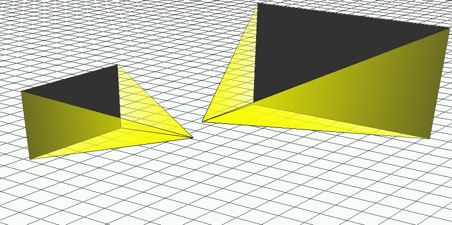
The key limitation of ubiquitous video is the incomplete coverage of the live video streams-every square meter of a space cannot be viewed from every angle with a live video stream at any chosen moment. For two cameras pointing in two rather different directions, when the user switches from viewing one camera to another, it is often not obvious how the subject matter in the two views relate to each other, nor is it obvious what is in the intervening space between the two cameras. To address this limitation, RealityFlythrough fills the intervening space between two cameras with older imagery (captured from the live camera feeds), and provides segues (i.e., transitions) between the two live cameras that sequences and blends the imagery in a way that provides the sensation of a human performing a walking camera pan. In certain scenarios the display of older imagery may be undesirable. While not ideal, transitions without background imagery are still sensible because the motion and timing of the transition and a background floor grid convey the distance and angle traveled. The user has complete control over how older imagery is displayed--whether it is displayed at all, in a sepia tone, or with an age-indicator-bar. The key untamed element of ubiquitous video is the imprecision of the sensed location and orientation of a camera (due to both sensor latency and sensor inaccuracy). Such imprecision gives misleading cues to the user about how the subject matter seen in one camera relates to the subject matter in another. For example, the images might appear farther apart than they really are. Under certain assumptions, offline vision techniques could perform seamless stitching [15]. To achieve real-time flythrough, this problem is instead handled by taking advantage of a property of the human visual system called closure [10]. Closure describes the brain's ability to fill in gaps when given incomplete information. It is a constant in our lives; closure, for example, conceals from us the blind spots that are present in all of our eyes. RealityFlythrough embraces closure by presenting the user with an approximate model of the relationships between two camera views, and having the user's visual cortex infer the relationships between the objects in the views. Dynamic transitions between still-images and live video feeds reveal the misregistrations in overlapping images (with an alpha blend), rather than hiding them through blending or clipping. Although this sacrificies aesthetics, the benefits obtained due to closure increase sensibility. For this technique to work, images must overlap. This property is sought by the mechanism that captures the older still-images for filling. The contributions of this paper are the RealityFlythrough architecture, and its evaluation along three dimensions: (1) its support for the desired abstractions for ubiquitous video, (2) its scalability, and (3) its robustness to changing user requirements that is the measure of every good architecture. The emphasis is on the architectural components that support the abstraction of infinite camera coverage. As will be shown throughout the paper, the architecture greatly reduces the complexity of the system, replacing complicated algorithms with concepts as simple as fitness functions. The design of a large-scale system that can accomodate thousands of cameras across multiple locations is considered in Section 7.3, but is not the focus of this paper. In many scenarios (most disaster response and SWAT scenarios), the size of the site and the availability of network bandwidth will limit the number of cameras that can be deployed. The architecture, as described, can easily handle these situations. The architecture has two unique qualities. First, it uniformly represents all image sources and outputs as Cameras, supporting a rich yet simple set of operations over those elements in achieving the desired abstractions. And, second, it employs a separate Transition Planner to translate the user's navigation commands into a sensible sequence of camera transitions and accompanying image blends. Our experiments show good support for the desired abstractions, as well as excellent scalability in the number of live video sources and Cameras. Support for evolution is explored through a series of changes to the application. The paper is organized as follows. Section 2 describes the user experience, and Section 3 compares our system to related work. Section 4 outlines the requirements of the system. We present a high level architectural overview of the system in Section 5, and then drill into the RealityFlythrough engine in Section 6 to reveal how the illusion of infinite cameras is achieved. Sections 7.1 and 7.2 evaluate the architecture's support of the system requirements, and Section 7.3 evaluates the architecture's tolerance to change and support for future enhancements. Section 8 concludes the paper.
|
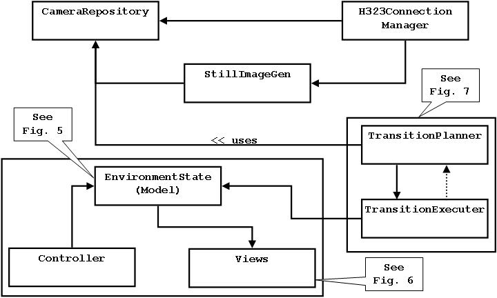 |
The RealityFlythrough Engine is the heart of the system. Given the available video streams and the user's intentions as input, the engine is responsible for deciding which images to display at any point in time, and for displaying them in the correct perspective. Fig. 4 shows the functional components of the engine. The standard Model-View-Controller design pattern [4] is used to represent and display the current system state. The Still Image Generator is responsible for producing and managing the still-images that are generated from the live camera feeds. These still-images are used to backfill transitions, but may also be worth viewing in their own right since they may not be much older than the live feeds. The Transition Planner/Executer is responsible for determining the path that will be taken to the desired destination, and for choosing the images that will be displayed along that path. The Transition Executer part of the duo actually moves the user along the chosen path. And finally, the Camera Repository acts as the store for all known cameras. It maintains a spatial index of the cameras to support fast querying of cameras.
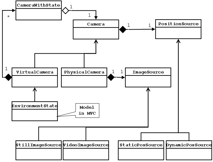
The objects that comprise the Model-View-Controller support the abstraction of infinite camera coverage. The key element of our abstraction is a virtual camera (Fig. 5) which is simply a location, an orientation, a field of view, and a list of the ``best'' cameras that fill the field of view. The notion of ``best'' will be explored in Section 6.3, but for now simply think of it as the camera that most closely matches the user's wishes. A virtual camera, then, can be composed of multiple cameras, including additional virtual cameras. This recursive definition allows for arbitrary complexity in how the view is rendered, while maintaining the simplicity suggested by the abstraction: cameras with an infinite range of view exist at every conceivable location and orientation.
 |
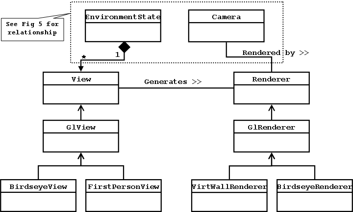 |
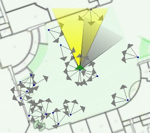
The Birdseye View not only provides a wide-area map view of the scene, but also reveals some of the rawness of ubiquitous video that is being abstracted away by the First Person View. The birdseye view makes the live camera coverage (or lack thereof) obvious and it reveals the ages and density of the still-images that are used for backfill (see Section 6.2). There are currently three display modes available in the birdseye view: (1) show all cameras, (2) show only the cameras that have been updated within some user specifiable interval, and (3) show only the live cameras. In an ideal environment, the user could ignore the information presented in the birdseye view because a live image would be present at every vantage point. A more typical scenario, and the one we adopted in the experiment described in Section 7, presents the user with the birdseye view that shows only the locations of the live cameras. The assumption, then, is that the intervening space is fully populated with still-imagery. In this mode, the illusion of infinite camera coverage is still present, but the user is given some extra insight into where live camera coverage is available.
Each view instantiates one or more renderers to actually render the cameras that are involved in the current state. Since the definition of a Virtual Camera is recursive, there may be multiple cameras that need to be rendered. Each of these cameras has a state associated with it: the opacity (intensity) at which the camera's image should be drawn for the alpha blend. There are currently two types of renderers: Virtual Wall Renderer and Birdseye Renderer.
The Virtual Wall Renderer is used by the First Person View. It renders images using the virtual wall approximation described in Section 2. The images are rendered in a specific order, on the appropriate virtual walls, and with the opacity specified in their state. The animation of a transition is achieved by moving the user's view point a set distance for each frame and progressing the alpha-blend for the overlapping portions of all of the images.
The Birdseye Renderer simply draws either the camera arrow or the frustum cone depending on the current state of the camera.
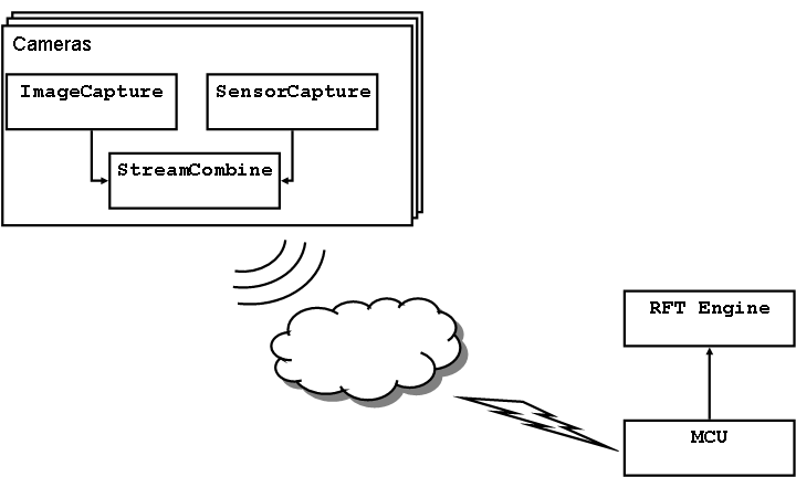
Key to the success of the infinite camera abstraction is the presence of sufficient cameras. If no imagery is available at a particular location, no amount of trickery can produce an image. To handle this problem, we take snapshots of the live video feeds and generate additional physical cameras from these. A Physical Camera consists of an Image Source and a Position Source (Fig. 5). The Image Source is a class responsible for connecting to an image source and caching the images. The Position Source, similarly, is responsible for connecting to a position source and caching the position. A camera that represents still-images, then, is simply a camera that has a static image source and a static position source. This is contrasted with live cameras that have a Video Image Source that continually updates the images to reflect the video feed that is being transmitted, and a Dynamic Position Source that is continually updated to reflect the current position and orientation of the camera.
To keep the still-imagery as fresh as possible, the images are updated whenever a camera pans over a similar location. Rather than just update the Image Source of an existing camera, we have chosen to destroy the existing camera and create a new one. This makes it possible to do a transitional blend between the old image and the newer image, without requiring additional programming logic. The images fit neatly into our Camera abstraction. We do not currently maintain a history of all still-images at a particular location, but it could be very useful to be able to move through time as well as space. We are moving to support this by saving video streams and allowing PVR-style (Personal Video Recorder) time-shifting.
The use of still-imagery to help achieve the abstraction of infinite camera coverage is of course imprecise. There are two ways that the limits of the abstractions are disclosed to the user:
First, the user has the option to never see older images. The user's preferences are used in the ``best camera'' calculation, and if no camera meets the criteria, the virtual camera will simply show a virtual floor grid.
Second, older images look different. The user can choose to have the old images displayed in a sepia tone, and can also choose whether or not to display an age-indicator-bar at the bottom of the sepia-toned or true-color images. The sepia tone makes it absolutely clear that the image is old, but it has the disadvantage that it alters the image, contradicting our aim to not mask reality. It is quite possible that this kind of image manipulation can hide information crucial to the user. An alternative is to show the age-indicator-bar on true-color images. The bar is bi-modal, giving the user high resolution age information for a short interval (we currently use 60 seconds), and lower resolution age information for a longer interval (currently 30 minutes). With a quick glance at the bottom of the screen, it is very easy for the user to get a sense of the age of an image.
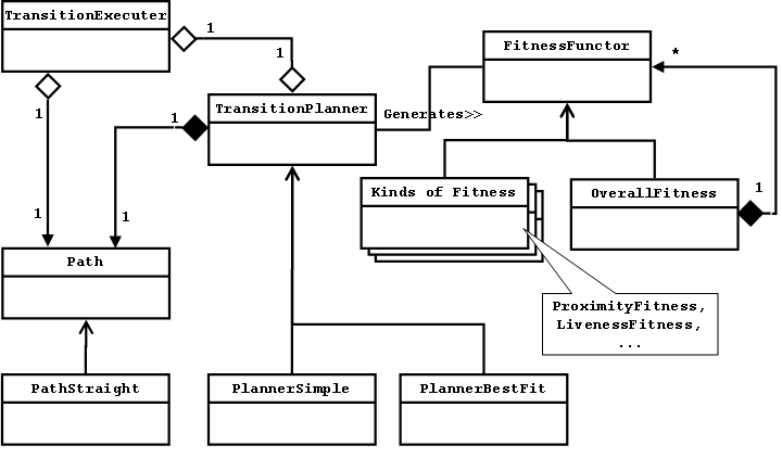
When the user changes views, the Transition Planner (Fig. 8) is responsible for determining the path through space that will be taken and the images that will be shown along this path. The Transition Executer is responsible for moving the user along the chosen path. There is a high degree of coupling between the planner and the executer because of the dynamic nature of ubiquitous video. Consider a typical case where the user wishes to move to a live camera. A naive approach would determine the location and orientation of the live camera, compute the optimal trajectory to get to the target location and orientation, determine the images to be shown along the path, and finally execute the plan that was just developed.
This approach does not work in a ubiquitous video environment for several reasons. The primary problem is that the destination camera may change its position and likely its orientation in the interval between when the plan was computed and when the execution of the plan has completed. The result will be a plan that takes the user to the wrong destination. Another problem is that the images that are selected along the path may not be the optimal ones. This is because the cameras that provide the intervening imagery may be live cameras as well, in which case their locations and orientations may have changed in the time since the plan was created. The result is that a live image that could have been shown is missed, or perhaps worse, a live image is shown that can no longer be seen from the current vantage point, so instead no image is displayed. Another possibility is that the dynamically generated still-imagery is updated after the plan is generated, but the older image is displayed instead.
To account for all of these problems the transition planning needs to be done dynamically and interleaved with the execution. There are a number of competing issues that need to be balanced when doing dynamic planning. It would seem that the ideal is to construct a plan at every time step, but some parts of the planning process are computationally expensive and need to be done sparingly. Also, the user needs to be given time to process the imagery that is being displayed, so even if a better image is available, showing it immediately may actually reduce comprehension.
The solution is to first introduce a dynamic Path object that takes a Position Source rather than a Position as its destination. The destination is now a moving target. At every time step, the Path can be queried to determine the current trajectory. With this trajectory, the Transition Planner can look ahead some interval and determine the best image to display. This image (camera, really) is added to the end of the camera queue. Each Virtual Camera--and since the Transition Planner acts on the Environment State remember that the Environment State is a virtual camera--maintains a fixed-length queue of cameras. When the queue is filled and a new camera is added, the camera at the front of the queue (the oldest or least relevant camera) is popped off the queue and thus removed from the Virtual Camera. The new camera that is added has a time-based opacity which means that the opacity gradually increases with time. We currently have the image blend to full opacity in one second.
This approach results in what appears to be a transition from one image to another, but along a dynamically changing path and with images that were used earlier still being displayed (if in view) to provide additional contextual information. The piece of the puzzle that is still missing is how the plan is constructed and adjusted dynamically. The Transition Executer (Fig. 8) is responsible for querying the Path at every time step and moving the user along the desired trajectory. It is also responsible for notifying the Transition Planner at time intervals set by the planner. These notification events give the planner the opportunity to determine which image (if any) to display next. Time is being used for signaling instead of ``destination reached'' because having the Path be dynamic means the destination may never be reached. Time is an adequate approximation of this signal point.
To determine the images to show during a transition the Transition Planner applies a series of Fitness Functors to each camera in the neighborhood. The Fitness Functors are weighted based on user preference. Some of the fitness dimensions are: proximity (how close is the camera to the specified position), rotation and pitch (how well do the orientations match), screen fill (how much of the screen would be filled with the image if it were displayed), recency (how recently was the image acquired), and liveness (is the camera live or not).
To further increase the sensibility of transitions, three heuristics are used to decide which images to display: (1) The current image should stay in view for as long as possible, (2) once the to image can be seen from the current position, no other images should be displayed, and (3) there should be a minimum duration for sub-transitions to avoid jumpiness. The first two items are handled by always applying the Fitness Functors to the current camera and the ultimate target camera regardless of whether they pass the ``in the neighborhood test'', and then boosting the fitnesses by a configurable scalar value. This has the effect of giving extra weight to the current and target cameras, thus indirectly satisfying our heuristics. The third item is handled by adjusting the time interval used for Transition Planner callbacks.
The CameraRepository is simply a container for all of the cameras (including the still-cameras) that are known to the system. To support efficient spatial querying of the cameras, an R-Tree [5] is used to store the camera locations. The exact locations of the live cameras are not stored in the index because this would cause continuous updates to the index, and such precision is not necessary when doing ``get cameras in neighborhood'' queries. Instead, only location updates that are greater than a configurable threshold result in a replacement in the spatial index.
Each physical camera has certain fixed memory costs. To minimize the use of limited OpenGL resources, the cameras share a pool of texture maps. We have to store the image somewhere, though, so each camera (Image Source, really) allocates 768KB to store a 512x512 image (the size is dictated by OpenGL's texture map size requirements) at a depth of 24bits. After a period of inactivity, the Image Source frees memory by storing the image to disk. Under normal loads, there is no perceptible difference in performance when an image is read from disk.
An architecture must be evaluated along two dimensions: does it work, and will it work in the future? In this section we first present a formative user study that captures the essence of the user experience and helps show that the abstractions presented are compelling and useful. Second, we examine performance to get insight into the scaleability of the system. Third, to evaluate how well the architecture will accommodate future changes to the application, we examine its robustness against a set of significant changes and extensions.
An earlier paper on RealityFlythrough [12] suggested that the first-person perspective used in transitions generated a sense of ``being there''. We re-ran this experiment using our new architecture which was designed to better handle the dynamic nature of a ubiquitous environment. Unlike the first experiment where the still-images were painstakingly pre-inserted, this run made full use of the automatic still-image capture described in Section 6.2. This user study and the one described in the earlier paper were formative studies designed to provide evidence that RealityFlythrough research is headed in the right direction.
To determine how the system was perceived by users, we repeated the earlier experiment as closely as possible. We used the same subjects, the same equipment on the user end, and the same location for the flythrough.
There were three hand-carried camera units in the field. They
consisted of a standard logitech web camera (![]() $100), a WAAS-enabled
Garmin eTrex GPS (
$100), a WAAS-enabled
Garmin eTrex GPS (![]() $125), a tilt sensor manufactured by AOSI
(
$125), a tilt sensor manufactured by AOSI
(![]() $600), and an 802.11b equipped laptop. The tilt sensor provides
compass, tilt, and roll readings at
$600), and an 802.11b equipped laptop. The tilt sensor provides
compass, tilt, and roll readings at ![]() 15hz. The video streams were
transmitted using the OpenH323 video conferencing standard at CIF
(352x288) resolution.
15hz. The video streams were
transmitted using the OpenH323 video conferencing standard at CIF
(352x288) resolution.
The subjects' task was to remotely explore our campus food court with the goal of getting a sense of what is happening, and to determine if there is anything to draw them to the site for lunch. The experiment was run twice because some problems with the system were encountered on the first run. We discuss this first experiment because the problems are revealing.
The first run of the new experiment was very positive from a technical standpoint. Three video streams connected successfully, and a large number of still-images were automatically generated, quickly filling the entire region with cameras. Only 61 pre-configured still-images were used in the earlier version of the experiment, but 100's were generated in this one, greatly increasing the camera density. Despite the extra overhead incurred by auto-generating the images and by planning transitions on the fly, the system performance felt about the same. In fact, the subjects made the statement that the ``performance was definitely much nicer.'' The new H263 video codec proved to be far superior to the H261 codec used previously. The frame rate varied by scene complexity, but appeared to average about 6-8 frames per second. The frame size was the same as was used previously, but the image quality was better and the colors were much more vivid. The generated still-images were clear and of good quality. On several occasions the subjects rapidly pointed out the age of images, indicating the success of the age indicator bar.
Even with all of these improvements, though, the subjects were not left with a positive impression and had to conclude that ``from a usability standpoint, it went down.'' Transition sequences were met with comments like ``it seems like it's awkward to move through several of those stills'', and ``[that] transition wasn't smooth.'' Post-experiment analysis identified three sources for the problems: (1) Too many images were being presented to the user, not allowing time for one transition to be processed mentally before another one was started. (2) The attempt to acquire a moving target resulted in an erratic path to the destination, causing disorientation. And, (3) no attempt was made to filter the location data by sensor accuracy. Still-images were being generated even when the GPS accuracy was very low, so transitions involved nonsensical images which detracted from scene comprehension.
Fortunately, none of these problems were difficult to handle. In Section 7.3 we will discuss the actual modifications made because these unplanned changes exemplify the architecture's robustness to changing requirements.
The experiment was repeated with much more positive results. Despite worse conditions at the experiment venue (we shared the space with a well attended Halloween costume contest), the subjects had much more positive comments such as, ``Let's try one in the completely opposite direction. That was pretty nice.'', and ``It's pretty accurate where it's placing the images.'' ``That was kind of cool. They weren't quite all in the same line, but I knew and felt like I was going in the right direction.''
The costume contest placed some restrictions on where the camera operators could go, forced them to be in constant motion, and resulted in a lot of close-range video footage of people's backs (the cameras were being held at chest level). The constant motion may be typical with head-mounted cameras, and should be adressed seriously. The subjects found the constant motion to be annoying (``they're all over the map''), and the motion placed quite a strain on the new algorithm used to home in on a moving target. The subjects actually preferred the calmness of the still-images. Midway through the experiment, we asked the operators to slow down a bit, and the experience improved dramatically: ``Yeah, that's what it is. So long as [the camera operators'] rotation is smooth and slow, you can catch up to it and have smooth transitions.''
We have since experimented with ways to reduce the amount of motion that is experienced during transitions. The fact that our subjects preferred the calmness of the still-images is revealing. There were simply too many sources of movement in our transitions, making them difficult to comprehend and aesthetically unappealing. When we move through the real world we only have to take into account 6 dimensions of movement--our own movement in three dimensions and the movement of the objects we are viewing in three dimensions. During a transition involving a moving camera, however, the camera is moving independently and so represents another three dimensions that have to be processed. Each additional moving camera being displayed adds three more dimensions. There is simply too much movement to process. The solution we have adopted involves pausing the live video streams whenever they come into view during a transition, and playing them back at increased speed once they have been acquired. This approach will be described in more detail in Section 7.3.
By measuring the performance of the system we hope to provide some insight into the scalability of the architecture. Raw performance metrics mainly measure the speed of the hardware and the quality of the compiler. Seeing how the raw numbers vary under certain conditions, however, reveals important details about the architecture.
The experiments with RealityFlythrough described thus far have only been run using at most three video streams. To determine the maximum number of simultaneous streams that can be handled by the server, we ran some simulations. The capacity of the wireless network forms the real limit, but since network bandwidth will continue to increase, it is instructive to determine the capacity of the server. We should estimate the capacity of a single 802.11b access point to give us a sense of scale, however. For the image size and quality used in the user studies, the H263 codec produces data at a relatively constant 200Kbps. Empirical study of 802.11b throughput has shown that 6.205Mbps is the maximum that can be expected for applications [17]. This same study shows that the total throughput drops drastically as more nodes are added to the system. With more than eight nodes, total throughput decreases to roughly 2Mbps. This reduction means we cannot expect to have more than 10 streams supported by a single 802.11b access point.
We will see that the bottleneck on the server is the CPU. As more compressed video streams are added to the system, more processor time is required to decode them. Some of the other functional elements in RealityFlythrough are affected by the quantity of all cameras (including stills), but the experimental results show that it is the decoding of live streams that places a hard limit on the number of live cameras that can be supported.
The machine used for this study was a Dell Precision 450N, with a 3.06Ghz Xeon processor, 512MB of RAM, and a 128MB nVidia QuadroFX 1000 graphics card. It was running Windows XP Professional SP2. The video streams used in the simulation were real streams that included embedded sensor data. The same stream was used for all connections, but the location data was adjusted for each one to make the camera paths unique. Because the locations were adjusted, still-image generation would mimic real circumstances. No image processing is performed by the engine, so replicating the same stream is acceptable for this study. The image streams were transmitted to the server across a 1 Gbit ethernet connection. Since the image stream was already compressed, very little CPU was required on the transmitting end. A 1 Gbit network can support more than 5000 simultaneous streams, far more than the server would be able to handle. Network bandwidth was not a concern.
To obtain a baseline for the number of streams that could be decoded by the server, we decoupled the MCU from the engine. In the resulting system, the streams were decoded but nothing was done with them. With this system, we found that each stream roughly equated to one percent of CPU utilization. 100 streams used just under 100 percent of the cpu. The addition of the 113th stream caused intermittent packet loss, with packet loss increasing dramatically as more streams were added. The loss of packets confirmed our expectation that the socket buffers would overflow under load.
Having confirmed that the addition of live cameras had a real impact on CPU utilization, we added the RealityFlythrough engine back to the system. We did not, however, add in the still-image generation logic. To determine the load on the system we looked at both the CPU utilization and the system frame rate as new connections were made. The system frame rate is independent of the frame rates of the individual video feeds; it is the frame rate of the transitions. It is desirable to maintain a constant system frame rate because it is used in conjunction with the speed of travel to give the user a consistent feel for how long it takes to move a certain distance. As with regular video, it is desirable to have a higher frame rate so that motion appears smooth. To maintain a constant frame rate, the system sleeps for an interval between frames. It is important to have this idle time because other work (such as decoding video streams) needs to be done as well.
|
For this experiment, we set the frame rate at 15fps, a rate that delivers relatively smooth transitions and gives the CPU ample time to do other required processing. As Table 1 indicates, fifteen simultaneous video feeds is about the maximum the system can handle. The average frame rate dips to 14fps at this point, but the CPU utilization is not yet at 100 percent. This means that occasionally the load causes the frame rate to be a little behind, but in general it is keeping up. Jumping to 20 simultaneous connections pins the CPU at 100 percent, and causes the frame rate to drop down to 10fps. Once the CPU is at 100 percent, performance feels slower to the user. It takes longer for the system to respond to commands, and there is a noticeable pause during the transitions each time the path plan is re-computed.
To evaluate the cost of increasing the number of cameras, still-image generation was turned on when the system load was reduced to the 15 connection sweet spot. Recall that still-images are generated in a separate thread, and there is a fixed-size queue that limits the number of images that are considered. Still-images are replaced with newer ones that are of better quality, and there can only be one camera in a certain radius and orientation range. What this means is that there are a finite number of still-images that can exist within a certain area even if there are multiple live cameras present. The only effect having multiple live cameras may have is to decrease the time it takes to arrive at maximum camera coverage, and to decrease the average age of the images. This assumes, of course, that the cameras are moving independently and all are equally likely to be at any point in the region being covered.
The live cameras were limited to a rectangular region that was 60x40 meters. A still-image camera controlled a region with a three meter radius for orientations that were within 15 degrees. If there was an existing camera that was within three meters of the new camera and it had an orientation that was within 15 degrees of the new camera's orientation, it would be deleted.
We let the system get to a steady state of about 550 still-images. The number of new images grows rapidly at first, but slows as the density increases and more of the new images just replace ones that already exist. It took roughly 5 minutes to increase from 525 stills to 550. At this steady state, we again measured the frame rate at 14fps and the CPU utilization at the same 95 percent. The system still felt responsive from a user perspective.
These results indicate that it is not the increase in cameras and the resulting load on the R-Tree that is responsible for system degradation; it is instead the increase in the number of live cameras, and the processor cycles required to decode their images. This shows that the architecture is scalable. Since the decoding of each video stream can be executed independently, the number of streams that can be handled should scale linearly with both the quantity and speed of the processors available. Depending on the requirements of the user, it is possible to reduce both the bandwidth consumed and the processor time spent decoding by throttling the frame rates of the cameras not being viewed. This would reduce the number of still-images that are generated; a tradeoff that only the user can make.
The investment made in an architecture is only warranted if it provides on-going value; in particular it should be durable with respect to changing user requirements, and aid the incorporation of the changes dictated by those new requirements. Below we discuss several such changes, some performed, others as yet planned. Only one of these changes was specifically anticipated in the design of the architecture.
It should come as no surprise that the virtual camera metaphor inspired much of the present design, so there is a fairly straight-forward implementation to support it. The Virtual Camera is already a first class citizen in the architecture. To handle a stationary virtual camera, the only piece required is a Transition Planner that runs periodically to determine the ``best'' image to display. Part of the virtual camera metaphor, though, is supporting free motion throughout the space using video game style navigation controls. The difficulty we will face implementing this mode is in minimizing the number of images that are displayed to prevent the disorienting image overload. This problem was easily managed with the hitchhiking mode because a fixed (or semi-fixed) path is being taken. The path allows the future to be predicted. The only predictive element available in the virtual camera mode is that the user will probably continue traveling in the same direction. It remains to be seen if this is an adequate model of behavior.
Another measure of a good architecture is that it is no more complicated than necessary; it does what it was designed to do and nothing more. The plan to support a virtual camera mode explains why the Camera is used as the primary representation for data in the system. Once still-images, video cameras, and ``views'' are abstracted as cameras, they all become interchangeable allowing for the simple representation of complicated dynamic transitions between images.
In the time since our experiments were run, we have further improved the transitions by slightly modifying our approach to finding the next camera to display. Instead of looking ahead at a fixed time-interval, we now calculate when the current image will no longer be optimal--because it has rotated off-screen, it is zoomed in too near, or zoomed out too far--and use this time interval for selecting the next image. Each image is now displayed for an optimal amount of time. We still boost the fitness of the destination camera to reduce the number of images that are displayed as the transition nears completion. These changes were all confined to the Transition Planner.
Our current approach to this problem involves pausing the live video streams during a transition whenever they are visible on-screen. Once the destination camera has been acquired, the video stream is played back at increased speed until the users have caught up to the current time. This has two benefits: (1) it reduces the amount of motion that needs to be understood by the user during a transition, and (2) it pauses the moving target for an interval allowing for smoother final target acquisition. The video feeds are paused for only short durations (usually less than one second), so it does not take long for the user to catch up after the transition, and in early tests the pauses do not appear to be disruptive. The technique used for acquiring the moving target is still required because the target continues to move until it is actually visible on-screen.
Pausing of the video streams was handled by adding PVR-like (Personal Video Recorder) capabilities to the MCU. The incoming video streams are buffered to disk allowing for time-shifting and future replay of events. With this functionality added, the Transition Planner simply pauses and resumes the video feeds at the appropriate times.
This modification to the system should only affect the First Person View. Since we want to present the state information that is already available in the Birdseye View, that same information need only be re-rendered in a way that is consistent with the First Person View. If we want to create a wider field of view we could increase the field of view for the virtual camera that makes up the view. Another possibility is to generate additional views that are controlled by other virtual cameras. For example a window on the right of the display could be controlled by a virtual camera that has a position source offset by 45 degrees.
Sound will be treated like video. Each Physical Camera will have a Sound Source added to it, and new views supporting sound will be created. There might be a 3D Sound View which projects neighboring sounds, and a regular Sound View for playing the sound associated with the dominant camera.
With the latter approach we could also support connecting to multiple servers. The MCU is already capable of handling multiple incoming connections, so the main issue would be one of discovery. How would the viewer know what server/s could be connected to? What would the topography of the network look like? We leave these questions for future work.
It is not clear where still-image generation would occur in such a model. The easiest solution is to leave it where it is: on the viewing machine. This has the additional benefit of putting control of image generation in the individual user's hands. This benefit has a drawback, though. Still images can only be generated if the user is subscribed to a particular location, and then only if there are live cameras in that location. What if a user wants to visit a location at night when it is dark? It's possible that the users want to see the scene at night, but it is equally likely that they want to see older daytime imagery. If the still-images are captured server side, this would be possible.
Since server-side still-image generation may stress the architecture as currently specified, we consider it here. The engine would not have to change much. We would need a Still Image Generated listener to receive notifications about newly generated cameras. A corresponding Still Image Destroyed listener may also be required. The camera that is created would have a new Image Source type called Remote Image Source. The Position Source would remain locally static. The Remote Image Source could either pre-cache the image, or request it on the fly as is currently done. Performance would dictate which route to take.
We have presented an architecture for a system that harnesses ubiquitous video by providing the abstraction of infinite camera coverage in an environment that has few live cameras. We accomplished this abstraction by filling in the gaps in coverage with the most recent still-images that were captured during camera pans. The architecture is able to support this abstraction primarily because of the following design decisions:
(1) The Camera is the primary representation for data in the system, and is the base class for live video cameras, still-images, virtual cameras, and even the environment state. Because all of these constructs are treated as a camera, they can be interchanged, providing the user with the best possible view from every vantage point.
(2) The Transition Planner is an independent unit that dynamically plans the route to a moving target and determines the imagery to display along the way. New imagery is displayed using an alpha blend which provides the illusion of seamlessness while at the same time revealing inconsistencies. The system provides full disclosure: helping the user make sense of the imagery, but revealing inconsistencies that may be important to scene comprehension. Because the Transition Planner is responsible for path planning, image selection, and the blending of the imagery, it has a large impact on the success of RealityFlythrough. Having the control of such important experience characteristics in a single componenent and having many of those characteristics be user controllable is key to the sucess of the current design.
The architectural choices made during the design of RealityFlythrough are primarily responsible for the effectiveness of the system. Complex algorithms that select the appropriate cameras to display at any given point are reduced to constructs as simple as fitness functions. The seemingly complicated rendering of multi-hop transitions to moving destinations is simplified to the rendering of a virtual camera from different perspectives along a dynamically changing path. The algorithms are simple; the architecture makes them so.
Special thanks to Robert Boyer, Jennifer Carlisle, Adriene Jenik, Charles Lucas, Michelle McCurdy, Jonathan Neddenriep, and the Active Campus team for their help with this project, and to our shepherd, Nigel Davies, whose comments on the paper were invaluable. This work was supported in part by a gift from Microsoft Research and contract N01-LM-3-3511 from the National Library of Medicine.
This document was generated using the LaTeX2HTML translator Version 2K.1beta (1.48)
Copyright © 1993, 1994, 1995, 1996,
Nikos Drakos,
Computer Based Learning Unit, University of Leeds.
Copyright © 1997, 1998, 1999,
Ross Moore,
Mathematics Department, Macquarie University, Sydney.
The command line arguments were:
latex2html -split 0 -show_section_numbers -local_icons paper.tex
The translation was initiated by Neil McCurdy on 2005-05-03
|
This paper was originally published in the
Proceedings of the 3rd International Conference on Mobile Systems, Applications, and Services, Applications, and Services,
June 6–8, 2005 Seattle, WA Last changed: 20 May 2005 aw |
|